String Oscillator Synthesizer
Information in this manual is subject to change without notice and does not represent a commitment on the part of Applied Acoustics Systems DVM Inc. The software described in this manual is furnished under a license agreement. The software may be used only in accordance of the terms of this license agreement. It is against the law to copy this software on any medium except as specifically allowed in the license agreement. No part of this manual may be copied, photocopied, reproduced, translated, distributed or converted to any electronic or machine-readable form in whole or in part without prior written approval of Applied Acoustics Systems DVM Inc.
Copyright ©2018 Applied Acoustics Systems DVM Inc. All rights reserved. Printed in Canada.
Program Copyright ©2005-2018 Applied Acoustics Systems, Inc. All right reserved.
String Studio VS is a Trademark of Applied Acoustics Systems DVM Inc. Windows and Windows Vista are registered trademarks of Microsoft Corporation in the United States and other countries. Mac OS and Audio Units are registered trademarks of Apple Corporation. VST Instruments and ASIO are trademarks of Steinberg Soft Und Hardware GmbH. AAX is a registered trademarks of Avid Technology Inc. All other product and company names are either trademarks or registered trademarks of their respective owner. Unauthorized copying, renting or lending of the software is strictly prohibited.
Visit Applied Acoustics Systems DVM Inc. at www.applied-acoustics.com
String Studio VS is a virtual analog synthesizer that combines into a modern instrument features of the legendary vintage synthesizers. String Studio VS generates sound by simulating the different components of the synthesizer through physical modeling. This technology uses the laws of physics to reproduce how an object or system produces sound. In the case of String Studio VS, mathematical equations describing how analog circuits function are solved in real-time. String Studio VS therefore uses no sampling or wavetable, it just calculates the sound as you play in accordance with the controls it receives. This sound synthesis method ensures unmatched sound quality, realism, warmth and playing dynamics.
String Studio VS offers a wide range of performance features, including keyboard modes, portamento, vibrato and legato functions, a programmable pattern arpeggiator, and a complete set of MIDI features for optimal controller integration.
This synthesizer is entirely based on the AAS physical modeling technology and uses no sampling nor wave tables. Instead it produces sound by solving, on the fly, mathematical equations modeling the different components involved in string instruments and how they interact. This elaborate synthesis engine responds dynamically to the control signals it receives while you play thereby reproducing the richness and responsiveness of real acoustical instruments.
Before discussing the synthesizer in more detail, we would like to take this opportunity to thank you for choosing an AAS product. We sincerely hope that this product will bring you inspiration, pleasure and fulfill your creative needs.
The following minimum computer configuration is necessary to run String Studio VS:
Keep in mind that the computational power required by String Studio VS depends on the number of voices of polyphony and the sampling rate used. These computer configurations will enable you to play the factory sounds with a reasonable number of voices but performances will vary depending on your specific computer configuration.
Installation and authorization of String Studio VS is quick and easy. For the installation of our different products we use so-called custom installers which include both the program itself and your licence information. Installation and authorization can therefore be carried out automatically in a single step and from a single file when your computer is online. AAS products use a copy protection system based on a a proprietary challenge/response key exchange and therefore their authorization does not rely on other third party software and/or hardware.
In order to start the installation process, simply double-click on the installer file that you have downloaded. This will first install the program and then use the licence information included in the custom installer file to to carry out automatically the challenge/response procedure.
Once the installation is completed, you can check your licence information by starting the program and clicking the Settings button in the top right corner of the interface and then the About tab. You should see your serial number and the email address which you used in order to get the installer file. Note that your serial number is also sent to you by email when your custom installer is created.
If your computer is offline when running the installer, or if the authorization procedure could not be completed for another reason, the dialog box will will not show your serial number and you will be prompted to authorize the program. In that case, click on the Authorize button and follow the on-screen instructions. Note that it is possible to use the program during 15 days before completing the authorization process. After that period, the program will not function unless it is authorized.
String Studio VS comes with a standalone versions allowing you to play it without having to open your sequencer. This can be convenient to explore String Studio VS and its library, play it live or do some sound design work. To start String Studio VS in standalone mode, simply follow the instructions below:
Before you start exploring the program, take a moment to set up you audio and MIDI configuration as explained below.
Audio and MIDI configuration tools are accessed from the hardware tab in the settings window which is accessed by clicking the Settings button in top right corner of the interface. This setting tab first allows you to select an audio output device from those available on your computer. Multi-channel interfaces will have their outputs listed as stereo pairs.
On Windows, the audio output list is organized by driver type. The device type is first selected from the Audio Device Type drop-down list. If you have ASIO drivers available, these should be selected for optimum performance. The Configure Audio Device button allows you to open the manufacturer’s setup program for your audio interface when available.
Once the audio input has been selected, you can then select a sampling rate and a buffer size from those offered by your audio interface.
The list of available MIDI inputs appears at the bottom of the dialog. Click on the checkbox corresponding to any of the inputs you wish to use.
String Studio VS comes with a factory library which amounts to a huge range of sounds before you have even turned a single knob. As you would expect, the best way of coming to grips with the possibilities String Studio VS offers is simply to go through the sounds one at a time.
A sound or preset is a stored set of parameters corresponding to a given sound. The programs are grouped and organized in packs which are represented by an icon in the top left corner of the interface. The names of the currently loaded pack and sound are displayed at the top of the interface.
One navigates among the different packs and sounds with the associated drop-down menu which is opened by clicking on the pack icon or sound name. One can also browse sounds by using the left and right arrows which appear just before the Compare button in the top part of the interface. One can also use the computer keyboard arrows.
Sounds are managed using the Sound Manager which is revealed by clicking on the down-pointing arrow located just before the Compare button. Playing sounds and organizing them is pretty straightforward, please refer to Chapter 3 for a complete description of the pack and sound management operations.
String Studio VS integrates seamlessly into the industry’s most popular multi-track recording and sequencing environments as a virtual instrument plug-in. String Studio VS works as any other plug-in in these environments so we recommend that you refer to your sequencer documentation in case you have problems running String Studio VS as a plug-in. Note that in plug-in mode the audio and MIDI inputs, sampling rate, and buffer size are determined by the host sequencer.
AAS technical support representatives are on hand from Monday to Friday, 9am to 6pm EST. Whether you have a question on String Studio VS, or need a hand getting it up and running as a plug-in in your favorite sequencer, we are here to help. Contact us by phone or email at:
Our online support pages contain downloads of the most recent product updates, and answers to frequently asked questions on all AAS products.
Throughout this manual, the following conventions are used:
The String Studio VS synthesis engine is inspired by the functioning of string instruments as illustrated in Figure 1. As in a real instrument, it is the vibration from the string which constitutes the main sound production mechanism. The string is set into motion by the action of a hammer, a pick or a bow. The frequency of the oscillation is determined by the effective length of the string which is controlled by the finger/fret interaction. A damper can be applied on the strings in order to reduce the decay time of the oscillation. This is the case on a piano, for example, when felt is applied on the strings when the keys and the sustain pedal are released.

In terms of signal flow, this is similar to the familiar pattern of an analog synthesizer where waveforms from an oscillator are sent into filters and effect processors. In the case of String Studio VS, the sound source is a so-called string oscillator whose signal is filtered by the Filter and Body modules and then processed by a multi-effects module as illustrated in the signal flow diagram of Figure 2. String Studio VS provides three type of oscillators, a bowed string oscillator (BSO), hammered string oscillator (HSO), and a plucked string oscillator (PSO).

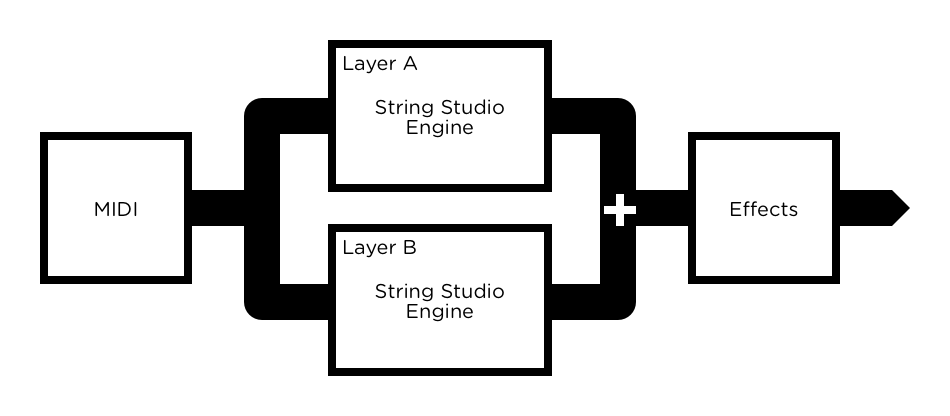
String Studio VS is a multitimbral synthesizer which can play two different timbres simultaneously either in layered or split keyboard mode. The general architecture of the synthesizer is shown in Figure 3 and consists of a MIDI routing module, two independent String Studio VS engines in parallel, a mixer, and a multi effects module.
The top part of the interface is called the Utility section and is shown in Figure 5. This section first includes the Sound Manager which is used to access and manage sounds and sound packs and will be described in details in Chapter 3. Just below is the Layer Mixer which allows one to adjust and monitor the level of the Master Volume and that of each layer. This section also includes the MIDI LED as well as the History and Settings commands. These tools are described further in Chapter 5.


The graphical user interface of each synth engine is identical and has been organized around three different views as shown in Figures 6, 7 and 8.
The first view, called the Play view of the instrument, gives access to different performance parameters as well as to a step sequencer. The second and third views, called the Synth and Effects views respectively, are used for in-depth editing of the synthesis and effect parameters. One can switch from one view to the other by using the Play, Synth and Effects tabs located just below the layer mixer. The modules included in these different views are explained in details in Chapter 4.
Finally, there is also a Browse tab which is used to access the Layer Browser which will be described in Chapter 3.
The size of the interface can be adjusted by click-dragging the lower right corner of the interface or by choosing specific size ratios in the Settings window accessed by clicking on the Settings button in the utility section. This is useful to find the optimal size of the interface depending on your display and its resolution.
The lower section of this view includes a master clock, keyboard, unison, glide, vibrato and arpeggiator modules which will be described in more details in Chapter 4.
On the left of these parameters, one finds a pitch bend wheel and two modulation wheels. The modulation wheels are used to control parameters in real-time through the use of Modulator modules which will be described in Chapter 4. Just below is a clickable seven octave ribbon allowing one to play different notes on the range of the piano which can be useful when no MIDI keyboard is connected to the computer.
The top section of this view allows one to turn the effects from the multi-effects module, compression and equalizer on and off and to rapidly adjust their main parameters.

The Synth view gives access to the synthesis parameters described in details in Chapter 4 and allows one to really go under the hood. One can switch between different synthesis modules using the buttons appearing at the bottom of this view.

The Effects view includes an equalizer, a compressor a multi-effects, and a reverb module. The multi-effects module consists in two effects in series. The effect list includes a delay, distortion, chorus, flanger, phaser, wah wah, auto wah, a notch filter, a guitar amplifier, and a tremolo. The functioning of the effect modules is described in details in Chapter 4.

In the context of String Studio VS-3, a sound is a preset for the parameters of the entire synthesizer. Sounds are created by combining layers, corresponding to different instances of the synthesis engine, and effects. In this section we first review the browsing of sounds and their organization into Sound Packs. We then review the so-called Layer Browser which is used for the creation of new sounds. Finally we explain how to backup and share sounds and how to import sounds from String Studio VS-2.
Sounds are stored in packs which basically act as folders. The name of the sound currently loaded is displayed at the top of the interface along with the name of the corresponding sound pack and its associated image as shown in Figure 9.
The list of available packs is viewed by clicking on the the pack image. A pack is selected by navigating through the list and clicking on a new image. The list starts with an AAS section comprising the factory library shipped with the program and AAS expansion sound packs which may be installed on your computer. This list is followed by a User section which includes all other packs created by the user. The packs in the AAS section have read-only permission which means that their content can not be modified. These sounds from the AAS section can be edited but the new versions need to be saved into a user pack as will be explained in the section below.
The list of sounds in a given pack is revealed by clicking on the name of the sound. Clicking on a new name in the list loads this new sound into the synthesizer. One can also navigate through the list of sounds using the left and right-pointing arrows located on the right of the sound name. Note that after clicking on the name of the sound or the left or right-pointing arrows, a keyboard icon appears to the right of the sound name. This icon indicates that the arrows of the computer keyboard can also be used to navigate through the list of sounds. This feature is de-activated as soon as one clicks in another region of the interface.

Sounds are saved by clicking on the Save or Save As buttons located to the right of the navigation arrows in the top part of the interface (see Figure 9). When a sound has just been loaded, the Save button is greyed out and is therefore inactive. It is activated as soon as any parameter on the interface is modified. Clicking on this command replaces the stored version of the sound with the new one.
The Compare button, located just before the Save button, also becomes active as soon as a sound is modified. This command allows one to compare the modified version of a sound with the original version. This is useful when deciding if a sound should be replaced by a new version. Note that once the button has been switched on all further modifications to a sound are blocked. In order to allow edition again, the command must be switched off.
A new copy of a sound is saved by using the Save As command which is activated by clicking on the corresponding button which opens the Save Sound pop-up window. The name of the sound is entered at the top of this window. The destination pack is then selected. If necessary, a new pack can be created by clicking on the New Pack button. Sounds are saved with a Category and Tone Quality attribute. These are selected by using the corresponding drop-down lists. These attributes are useful for searches and display as will be described in the next section. These are followed by an entry for the name of the sound creator and finally a section for notes which can be useful for a description of the sound or playing indications.
Sounds and sound packs are managed using the Sound Manager which is opened by clicking on the down-pointing arrow button in the top part of the interface (see Figure 9). It is closed by clicking again on the same button or clicking on the cross icon appearing in the top left corner of the sound manager. On the left of the sound manager window, one finds the list of sound packs. The list of sounds included in the currently selected sound pack is displayed to the right of the pack list.

Commands which can be applied on sound packs are listed in the pack command drop-down menu revealed by clicking on the down-pointing triangle located at the top of the sound pack list. A new sound pack is created by choosing the New command which opens the New Pack window. One then enters a name for the pack and clicks on the Create button. This creates an empty pack in the user section of the pack list. In order to rename a pack, select it, click on the Rename button and simply enter a new name. A pack is deleted by selecting it and then choosing the Delete command.
Packs and the information corresponding to their sounds are stored in files on your computer hard disk. In order to view these pack files, click on the Show Packs Folder command. On the Windows operating system, this command will open an Explorer window at the location where the files are stored while on Mac OSX, the command opens a Finder window. All the pack file names follow the same format which consists of the pack name followed by the VS-3 Pack extension. These files can be used for backups or to exchange sounds with other users.
When sounds are deleted from a pack, a safety copy is created in the so-called Trash pack. By default, this pack is not visible in the list of packs. In order to make it visible one clicks on the Show Trash command. This special trash pack always appears at the very end of the user pack list. This pack is useful to retrieve a sound which may have been deleted by mistake. Note that when deleting a pack, the sounds included in that pack are not copied to this Trash pack. In order to retrieve a deleted pack, click on the Show Packs Folder command and go to the Deleted folder. This backup folder includes a copy of packs which were deleted. If a pack was deleted by mistake and you still want to use it or retrieve some sounds from it, move it back to the Packs folder and it will appear again in the sound manager with all its content.
The list of sounds included in the selected pack is displayed to the right of the sound pack list, the currently active sound being highlighted. Clicking on another sound name loads the corresponding preset data into the synthesizer and changes the current sound selection. The list of commands which can be applied on sounds are listed in the sound command drop-down menu which is opened by clicking on the down-pointing triangle located at the top of the sound list.
The list of sounds can be presented in different ways by using the Arrange by command. Using the Category option, groups the sounds by category, the categories being displayed in alphabetical order. One can jump from one category to the other by clicking on the category name at the top of the list display and choosing a new category. Within a category, sounds are further sorted using the Quality attribute and then by alphabetical order. Using the Index option lists the sounds by index values. The index of a sound in a user pack can be changed by using the Up and Down buttons which appear on the top right corner of the sound list. Choosing the None options results in all the sounds from the current sound pack being displayed as a flat list. This list can further be arranged by using the Category, Creator, Date, Index, Name, and Quality attributes.
Information for individual sounds is shown by clicking on the Info button which opens the Information display box. This includes the name of the sound, its category, tone quality, and its creator. All these fields can be modified directly from this Information window. There is also a Notes field which is useful for entering a description or playing instructions. Note that the fields in this window can be edited for many sounds at once when using multiple selection of sounds.
A multiple selection consisting of adjacent sounds is obtained by clicking on the name of the first sound to be selected and then, holding down the Shift key on the computer keyboard, and the clicking on the name of the last one. A non-adjacent multiple selection is obtained by holding down the Ctrl/Command computer key and clicking on the name of the different sounds to be selected. All sounds from a pack can also be selected at once by using the Select All command from the command drop-down menu.
A sound can be copied to another pack by selecting it and using the Copy command. This command is available from the command drop-down menu or by right-clicking on the selected sound. The destination pack is then selected by clicking on its image and the sound copied by using the Paste command. A sound is deleted in exactly the same way but using the Delete command which is also available both from the command drop-down menu and right clicking on a selected sound. A sound can also be moved to another pack by selecting it and then dragging and dropping it onto the image of a pack. Be careful however as this command, unlike the copy command, copies the selected sound to the destination pack but also deletes it from the original pack. Note that the copy, delete, and move commands can be applied on single sounds or multiple selections.
User packs are stored on disk as files which contain all the information corresponding to the sounds they include. These files can be displayed directly from String Studio VS by opening the sound manager and clicking on the Show Pack Files command from the command drop-down menu at the top of the pack list. This will open an Explorer or Finder window on Windows or Mac OS respectively at the right location.
The simplest way to create a backup of your packs is to make a copy on an external media of the above mentioned folders. Individual packs can be backed-up by making copies of individual pack files.
Note that, as mentioned above, safety copies of deleted sounds are created in the Trash pack. This pack can be emptied from time to time by selecting it and deleting its sounds. A safety copy of deleted packs is also automatically created in a special Deleted sub-folder located in the pack folder mentioned above.
Sounds can easily be shared with other String Studio VS users. This operation simply involves the exchange of the above mentioned user pack files. When a new pack file is copied to the pack folder on the destination computer, it is automatically available in String Studio VS.
Note that individual sounds can not be exported. Sounds always appear inside a pack file. If you only wish to share a few sounds, create a new pack, copy the sounds you wish to exchange to this pack and share the corresponding pack file.
Sounds in String Studio VS-3 consist of one or two layers, each layer corresponding to one instance of the String Studio VS synthesis engine. Sounds can be modified by changing individual parameters in the Synth section of each layer but they can also be changed by loading presets for the entire synthesis engine corresponding to each layer. Presets for each layer slot are loaded using the Layer Browser, shown in Figure 11. It is opened by clicking on the Browse tabs located just below the layer mixer.

Layer presets for a given sound can be imported from another sound or come from layer presets previously saved by the user. Layers from other sounds are displayed by clicking on the Sounds button in the top left corner of the layer browser while user saved presets are displayed by clicking on the Saved Layers button.
Layer presets from library sounds are browsed by pack. The list of layers included in the selected pack are displayed on the right of the pack list. Layers are organised in sound categories and are listed using the name of the sound they come from and their associated slot (layer A or layer B). One can jump from one sound category to another by using the category drop-down menu at the top of the layer list. Layers can have a label but this is optional. The label is the name appearing in the displays just above the gain sliders in the layer mixer. One can edit this name by clicking on this display. When a layer has no label the default labels Layer A and Layer B appear in the layer mixer.
As soon as one selects a new layer in the list, the corresponding preset is loaded into the layer slot. In other words, the tone played by the corresponding synthesis engine is changed. Different tones can be tried by selecting different layer presets in the browser. Different layer presets are selected by clicking on them or using the left and right arrows appearing at the top of the list or the computer keyboard arrows when the keyboard icon appears in the top of the list. To hear the changes, make sure the power switch of the corresponding layer, located just before the label name in the layer mixer, is in its on position. It may indeed be in its off position if you are editing a sound that initially had just one layer slot used. Note that as soon as a new layer is loaded into a sound, the Save and Save As buttons in the sound manager at the top of the interface become highlighted (in case of sounds from the AAS section, only the Save As button is highlighted since these sounds are read-only and therefore can not be modified). If you are happy with the changes and wish to keep them, use one of these commands.
For convenience, layer presets which you often use can be stored separately in a user section. These can simply be copies of existing layers or layers which were modified by tweaking the parameters in the Play, Synth, and Effects section of the synth engines and which you wish to keep for use in other sounds. The complete list of presets in this user section is displayed by clicking on the Saved Layers button in the upper left corner of the layer browser. Note that by default, this list includes a few basic or init presets which are very useful when creating a new sound from scratch. In order to save a new layer preset to this user section, use the Save Layer As command button located on the right of the layer browser in the Layer Utilities section and this will save the currently selected layer.
The Layer Utilities section of the layer browser includes other convenient commands. The Swap A and B command interchanges the complete set of parameters of each layer. This may be useful when testing different mixer settings. The Copy A to B and Copy B to A commands copy the complete set of parameters from one layer to the other. This results in the two layers of a sound being identical. This may be useful when wanting to create a sound with two slightly different layers or to quickly fill an empty layer with parameters. Note that in order to make these changes to a sound permanent, the Save or Save As commands must be activated using the buttons in the top of the sound manager.
String Studio VS-3 includes a converter that allows one to import sounds from String Studio VS-2. The conversion operation simply involves copying a String Studio VS-2 pack file into the String Studio VS-3 sound pack folder. The conversion operation is then triggered automatically when String Studio VS detects a pack from a previous version.
String Studio VS-2 sound packs, which were then actually called banks, can be found by opening String Studio VS-2, clicking on the Manage button at the top of the interface in order to open the manager and then clicking on the Show Files button at the bottom of the manager window.
While the great majority of sounds should be recuperated without noticeable differences, the conversion program is not infallible which means that some sounds might need some readjustments after the conversion. This is due to the fact that the mapping of the parameters from different versions of String Studio VS is not direct as a result of changes in the architecture, modules and the effect section between the different versions.
Note that AAS expansion sound packs for String Studio VS which were installed on your computer prior to the installation of String Studio VS-3 should not be converted in this way. The String Studio VS-3 installer you will have downloaded from our server should indeed also include your expansion sound packs and take care of their installation automatically. If this is not the case, or some packs are missing, please go back to your account on the AAS user portal and download the latest installer for these sound packs, they have indeed all been updated and optimized for this new version of String Studio VS.
This section can be used as a reference for the different controls appearing on the String Studio VS-3 graphical interface. This synthesizer is two-voice multitimbral and the different interface panels and modules are identical in each layer. This documentation therefore applies indifferently to both layers. We begin by describing the behavior of the different types of controls appearing on the interface and then describe the parameters of each module of the synthesizer.
The synthesizer parameters are adjusted using controls such as knobs, switches and numerical displays. A specific control is selected by clicking on it. A coarse adjustment is obtained by click-holding the parameter and moving the mouse, or the finger on a track pad, either upwards and downwards or leftwards and rightwards. The value of the parameter replaces its label while it is being adjusted.
Fine adjustment of a control is obtained by holding down a modifier key of the computer keyboard (Shift, Ctrl, Command or Alt key) while adjusting the parameter.
Double clicking on a knob brings it back to its default value when available.
Switches are turned on or off by clicking on them. They are used to activate or deactivate modules and the sync feature of some parameters.
Some displays reveal a drop-down menu when clicking on them. Adjustment of the control is obtained by clicking on a selection.
Different parameters can be modulated by the signal from different sources including the MIDI keyboard, envelope generators and the LFO modules. Modulation signals are controlled with small gain knobs located below the corresponding modulated parameters.
The Key modulation knobs are used to modulate a parameter depending on the note played on the keyboard. When in its center position, the value of the corresponding parameter is equal across the whole range of the keyboard. Turning the knob to the left increases the value of the parameter for low notes while decreasing its value for high notes. The variations are applied relative to the middle C (MIDI note 60) whose value is always that corresponding to the settings of the actual parameter knob. Turning the modulation knob to the right has the opposite effect and increases the value of the parameter for high notes while decreasing it for low notes.
The Vel modulation knobs are used to modulate the value of a parameter depending on the velocity signal received from the keyboard so that the value of a parameter increases as notes are played harder on the keyboard. The position of the knob is used to adjust the amount of modulation applied to the parameter. In its leftmost position, the modulation source is turned off and the value of the parameter does not vary with the velocity signal from the keyboard. Turning the knob clockwise increases the effect of the modulation signal on the value of the parameter.
Modulations using the signal from the LFO and Env modules are controlled using the LFO and Env gain knobs respectively. The amplitude of the modulation is zero when the knob is centered. It is increased by moving it from its middle position clockwise or counter-clockwise. When turning it counter-clockwise, the phase of the modulating signal is inverted while it is preserved when moving it clockwise.
The rate of the Arpeggiator, LFO and certain effect modules can be synchronized to the clock of a host sequencer when the program in used in plug-in mode. To do so, simply turn on their Sync switch. Synchronization values are adjusted with the Sync Rate parameter and range from 4 whole notes (16 quarter notes) to a thirty-second note (1/8 of a quarter note) where the duration of the whole note is determined by the host sequencer clock. The effect can also be synced to a triplet or dotted note. To adjust this parameter, click on the Sync Rate button and choose a rate value from the drop-down menu.
In standalone mode, when the Sync switch of an effect of module is switched on, the duration of a whole note is adjusted using the Rate control of the Clock module on the Play view.
The Play view is where the main performance oriented modules are located. Key parameters from the Synth and Effects view are also included for quick access. This view is loaded when starting the instrument and can be accessed from another view by clicking on the Play button on the top part of the interface.
The middle section of this view allows one to switch on and off the EQ, Compressor and Reverb as well as the active effect modules. Key effect parameters are also adjustable as presented in the description of the different effect modules in section 4.4


This module is used to control the tempo of the different effects of the FX section as well as that of the LFO and Arpeggiator modules when their respective sync button is switched on. When String Studio VS is launched in standalone mode the clock tempo, in bpm, is set by using the Rate knob. The tempo can also be adjusted by clicking at the desired tempo on the Tap Tempo pad of the module. Once the new tempo is detected, the value of the Rate knob is automatically adjusted.
When using String Studio VS in plugin mode, the Tap Tempo pad is replaced by a Sync To Host switch. In its on position, the rate is synchronized with that of the host sequencer. When switched off, the tempo is determined by the value of the Rate knob.

The Keyboard module controls how the synthesizer voices respond to the events coming from an external MIDI keyboard or from a MIDI sequencer.
The keyboard can be monophonic, allowing one to play only one note at a time, or polyphonic, allowing one the play chords. This behavior is adjusted using the Poly button. The keyboard is in polyphonic mode when this button is switched on.
The Tune control is used to transpose the frequency of the keyboard. This control is composed of two numbers separated by a dot. The first number indicates a value in semi-tones while the second one indicates a value in cents (one hundredth of a semi- tone). The amount of transposition can be adjusted by click-dragging upward or downward on the semi-tone and cent controls. Double clicking on these controls brings back their value to zero. When the value of the Tune parameters is set to 0.00, the frequency of notes are calculated relative to A4 with a frequency of 440Hz.
Note that in some cases, the frequency of the sound played may depend on the value of some of the synthesis parameters. For example, applying heavy dampers on the string may affect its pitch. In this case, the Tune parameter would be used to compensate this pitch difference and bring back the sound in tune.

The unison mode allows one to stack voices, in other words, play two or four voices for each note played on the keyboard. This mode creates the impression that several instruments are playing the same note together, adding depth to the sound. It is switched on by clicking on the LED located in the upper right corner of the module.
Each voice can be slightly detuned relatively to the others by using the Detune knob. Turning this knob clockwise increases the amplitude of the error. Furthermore, voices can be desynchronized by adding a small time lag between their triggering with the Delay knob. There is no delay when the knob is in its leftmost position and it increases (units in ms) as it is turned clockwise.

The Glide module is used to make the pitch slide between notes rather than changing immediately from note to note. The Time knob sets the amount of time necessary for the pitch to slide over one octave. The Mode drop-down menu enables one to choose between the Constant or Proportional mode. When in Constant mode, the time necessary for the pitch to slide from one note to another is always the same regardless of the interval between the notes. When set to proportional, the slide time becomes proportional to the width of the interval between the two notes.
Clicking on the Legato button switches the module into legato mode and the sliding between two notes then only occurs if the second note is played before the first one is released. When a note is played staccato, or in other words if a key is released before the next one is depressed, there is no glide effect. Note that even though the glide effect is available when the Key module is in polyphonic mode, it is mostly dedicated to monophonic playing. In polyphonic mode, the sames rules apply to individual voices and the overall result is less predictable.

String Studio VS includes two Modulator modules. These modules are used to assign external MIDI controllers to destination parameters. The idea behind these modulators is to make sounds as expressive and playable as possible. They allow the creator of a sound to determine which of the synthesis parameters are best suited for modulations while giving the user easy access to these parameters. There is no rule on the effect of each modulator but for the factory library modulator 1 is assigned mostly assigned to parameters controlling the pitch of the sound while modulator 2 is used to modulate the timbre of the sound.
The external MIDI controller linked to a modulator is specified by the user in the Macros section of the MIDI tab of the Settings window which is accessed by clicking on the Settings button in the upper right of the interface. Clicking on the drop-down menu associated with each modulator reveals a complete list of MIDI control changes numbers from which to choose from. If one does not know the MIDI control change number to use the Learn command, activated by clicking on the Learn button, can be used. When this option is turned on, the first MIDI cc number received by String Studio VS will be associated with this specific modulator. This assignment of external midi controllers, which should in principle correspond to a specific hardware set-up, is saved, in plug-in mode, with a sequencer project. In standalone mode, the last saved configuration is loaded when launching the program.
An external controller can be assigned up to four synthesis parameters. In order to choose destination parameters, click just below each of the module knob and a list of assignable parameters will appear. The module knobs control the gain applied to each of the destination modulation allowing one to control the amplitude of the modulation signal sent to each synthesis parameter by the external controller.
Modulators can quickly be disabled from the Layer Settings window which is opened by clicking on the gear icon located next to the Split button in the lower left corner of the Play panel. In order to deactivate a modulator, simply clik on the Modulator 1 or Modulator 2 button of Layer A or B. The modulator is reactivated by clicking again on the button. .
Note that certain parameters, for example those related to the string, can only be modulated upon a note on signal. They might therefore not work well with certain assignments for example with the channel pressure (monophonic aftertouch).

The vibrato effect is equivalent to a periodic low frequency pitch modulation. This effect is generally obtained by using an LFO to modulate the pitch signal of an oscillator. In String Studio VS , a dedicated module is provided for this effect. The Rate knob sets the frequency of the vibrato effect from 0.3 Hz to 10 Hz. The Amount knob sets the depth of the effect, or in other words the amplitude of the frequency variations. In its leftmost position, there is no vibrato and turning the knob clockwise increases the amount of pitch variation.
The vibrato can be adjusted not to start at the beginning of a note but with a little lag. This lag, in seconds, is set by the Delay knob. The Fade knob allows you to set the amount of time taken by the amplitude of the vibrato effect to grow from zero to the amount set by the Amount knob.

The Arpeggiator module allows one to play sequentially all the notes that are played on the keyboard. In other words, arpeggios are played rather than chords. The modules allows one to produce a wide range of arpeggios and rhythmic patterns and to sync the effects to the tempo of an external sequencer.
The arpeggio pattern is set by the combination of the value of the Range, Span and Order controls. This module is switch on by clicking on the small LED located in the upper right corner of the module.
The Range control is used to select the number of octaves across which the pattern is repeated. When the range is set to 0, there is no transposition and only the notes currently depressed are played. If set to a value between 1 and 4 (its maximum value), the notes played are transposed and played sequentially, over a range of one or more octaves depending on the value of the Range parameter. The direction of the transposition is set with the Span drop-down menu. This parameter can be adjusted to Low for downwards transposition, to High for upwards transposition or wide for transposing both upwards and downwards. Finally, the Order control sets the order in which the notes are played, therefore determining the arpeggio pattern. When set to Forward, the notes are played from the lowest to the highest. When set to Backward the notes are played from the highest to the lowest. In the two last modes, Rock and Roll exclusive and Rock and Roll inclusive, the notes are played forward from the lowest to the highest and then backward from the highest down to the lowest. When using the RnR exclusive mode, the highest and the lowest notes are not repeated when switching direction but in RnR inclusive mode these notes are repeated. Finally, in Chord mode, all the notes are played at once.
Rhythmic patterns can be added to the arpeggio pattern by using the 16-step Pattern display. Notes are played as the step display is scanned and the corresponding step is selected (red button on). Notes are played regularly when all the steps of the display are turned on and rhythmic patterns are created by selecting only certain steps. The arrow button below each step is used to fix looping points from which the rhythmic pattern starts being played again from the beginning.

The rate at which the arpeggiator pattern is scanned is set by the Rate knob of the Arpeggiator module or can be synced to the master clock of the Clock module. The Rate knob is only effective when the Sync control is set to off. When the Sync control is on, the rate (tempo) is fixed by the master Clock module (see 4.2.1) in standalone mode or the host sequencer in plugin mode. The rhythmic value of each step is set using the Steps parameter. Values can range between a quarter note and a thirty-second note with binary and ternary beat division options. One can then fix the metric of the pattern by setting the loop point of the step display appropriately.
The Arpeggiator module is toggled in latch mode by clicking the Latch button to its on position. In this mode, the Arpeggiator keeps playing its pattern when the notes on the keyboard are released and until a new chord is played.
The MIDI pitch wheel allows one to vary the pitch of the note played. The pitch wheel can be moved with the mouse but it is also automatically connected to the pitch wheel signal received from your MIDI keyboard.
The range of the pitch bend is 2 semi-tones up or down by default but can be changed. To adjust the range of the pitch bend, open the MIDI configuration window by clicking on the MIDI button located just below the MIDI led in the top part of the interface and use the Pitch Bend Range drop-down menu to select the range in semi-tones.
There are three wheels on the left of the Play panel. The first one is a pitch bend wheel while the two others are used to control the Modulator 1 and Modulator 2 modules respectively directly from the interface. Note that when a Modulator module is not assigned to any controller, the corresponding on-screen modulation wheel is disabled.
For more information on assigning MIDI continuous controllers to Modulator modules, please refer to section 6.2.5.
The lower part of this view includes a ribbon controller. The ribbon covers seven octaves and notes are played when clicking on the ribbon. The ribbon is useful to test sounds when no MIDI keyboard is connected to your computer.

When two layers are used in a sound, one can enable the split keyboard mode in order to play them in different regions of the keyboard. This mode is activated by clicking on the Split button. When this mode is activated, a coloured line appears above the ribbon keyboard of the interface in order to indicate the range of each split region of the keyboard. The left portion of the keyboard is associated with layer A while the right portion is associated with layer B. The split point on the keyboard can be adjusted in the Layer Settings window which is opened by clicking on the gear icon located next to the Split button. The split note can be chosen from the Split Note drop down menu. Alternatively, the Learn function can be activated and the desired split note played on the MIDI keyboard connected to String Studio VS.

Clicking on the gear icon located next to the Split button in the lower left corner of the Play panels opens the Layer Settings window. Command buttons allow one to quickly enable and disable external controller assignments used in conjunction with the Modulator modules of each layer. One can also turn on of off pitch bend and the sustain pedal (MIDI cc number 64) for each layer independently. Layer settings also include adjustment of the split note which is used when the split keyboard mode is used.
The different synthesis modules appear in this view. There is a total of ten modules organized into four groups. One can switch from module to module by using the buttons located at the bottom of the Synth view.
In a string instrument most of the sound we hear is radiated from the body of the instrument. The strings themselves radiate just a small amount of sound directly but it is their vibrations that are transmitted to the body of the instrument, through the bridge, where they can be radiated efficiently. It is also the strings that fix the pitch of the sound we hear depending on their effective lengths.

In a real string, the material of the string will affect how it vibrates. For example, a metal string will oscillate for a longer time than a nylon one; its sound will also be brighter. In the String module, this behavior is adjusted with the Damping and Decay knobs. The Damping knob is used to set the amount of high frequencies in the string vibration, this amount being increased as the knob is turned clockwise. The decay time of the vibrations is controlled with the help of the Decay knob and it is increased by turning the knob clockwise. Both of these parameters can be modulated with the pitch signal received from the keyboard.
In a first approximation, a string can be considered to be harmonic meaning that its partials are located at frequencies equal to multiples of its fundamental frequencies. Real strings, however, are more or less inharmonic depending mostly on the width of the string. This characteristic of strings is adjusted with the Inharm knob. When the Inharm knob is in its leftmost position, the string will be perfectly harmonic and turning the knob clockwise will increasingly detune the partials toward higher frequencies.
The Release knob is used to adjust the ratio between the decay time of the oscillation of the string when a note is depressed and when it is released. When the knob is in its rightmost position (value of 100%), both decay times are the same and equal to the decay time determined by the settings of the Decay knob. Turning this knob counter-clockwise will decrease the decay time of the note when it is released while keeping the decay time when the key is depressed to its current setting. Note that this control constitutes an easy mean to reproduce the action of dampers on the string. When the Damper module is used and the Release knob is turned to the left, the effect of the both damping mechanisms will add up.
Finally, the general level of the output signal from the String module is controlled with the Level knob. This parameter is proportional to the output signal from the body instrument sent into the distortion and the effects. It is therefore helpful to control the amount of distortion introduced by this modules and the different effects.
The String module can be played using different types of exciters in order to reproduce different types of instruments and playing techniques. The exciter is selected using the switches at the top of the module. The choices available are from left to right Bow, Hammer 1, Hammer2 and Plectrum. These different types of exciters share the same front panel but note that the names of the parameters controlled by the different knobs vary for each exciter. We now review the different exciter types in more detail.
The Plectrum exciter, illustrated in Figure 12, is used to play instruments such as guitars, harpsichords or basses with a pick. The Plectrum can be viewed as an angled object placed under the string and connected to a plate with the help of a spring. The purpose of the plectrum is to impose an initial displacement to the string before it is set into free vibration. As can be understood from figure 12, a vertical motion of the plate (which could be a hand holding the plectrum) will lift the string with the plectrum but will also result in a compression of the spring and an horizontal motion of the plectrum. The string will move with the plectrum until the protrusion (Prot) of the plectrum is equal to the compression of the spring and the string is released. The motion and behavior of the plectrum is controlled by adjusting the different geometrical and mechanical properties of the system.
The Prot knob is used to determine the protrusion of the plectrum with respect to the string while the stiffness and damping of the spring is controlled with the help of the Stiff and Damp knobs. The vertical velocity of the plectrum is adjusted with the Velocity knob. Note that the Prot, Stiff, and Velocity controls can be modulated with the pitch of the note played or the velocity signal from the keyboard.


The Hammer is used to play instruments such as the piano or other percussive instruments. With this exciter, the string is set into free vibration following a force impact with the hammer. The hammer can be used in two modes, Hammer 1 and Hammer 2, as illustrated in Figure 13. In the Hammer 1 mode, the hammer is located below the string and can only interact once with the string because of the action of gravity which brings it down after it has been raised to hit the string. In the Hammer 2 mode, the hammer is located above the string and can bounce on the string after the initial impact.
The illustration in Figure 13 shows that the action of the hammer can be modeled by the motion of a head connected to a mass. The mass of the hammer is adjusted with the Mass knob while the stiffness of the head is controlled with the Stiff knob. The velocity of the hammer when it hits the string is set with the velocity knob. The motion of the hammer can further be characterized by a damping coefficient, adjusted with the Damp knob, and controlling the absorption of the impact between the string and the hammer by the hammer. Note that this parameter is not related to the decay time of the string oscillation or the overall sound. On the contrary, the effect of this parameter may sometimes seem counter-intuitive even if it reproduces a physical property of the hammer. For example, increasing the damping of the hammer will make the compression of the spring linking the head to the mass harder and which will shorten the interaction between the hammer and the string but will also make it appear stronger resulting in a louder or longer sound.

The Bow exciter is used to play bowed instruments such as the violin, viola, or cello. The role of the bow is to set the string in self-sustained oscillation. Physically, oscillations of the string are maintained by a regular cycle of stick-slip movements. Due to friction forces between the string and the bow, the string sticks to the bow and follows its motion until the tension forces in the string, due to its own oscillating motion, break it free from the bow. The string is then in its slip phase and moves in the opposite direction to that of the bow. When the string motion changes direction once more, it sticks to the bow again, moving with the bow until it breaks free and repeats the cycle. Note that the frequency of this stick-slip motion is exactly the same as that of the string oscillation; or, in other words, the pitch of the note played.
The force with which the bow is applied on the string can be adjusted with the Force knob, the friction between the bow and the string is set with the Friction knob, and the velocity of the bow is controlled with the Velocity knob. The tone and behavior of the instrument are the results of a complex relationship between these parameters but some general rules can however be followed. As the force applied by the bow on the string is increased, the tone becomes more scrubby. The friction between the bow and the string usually determines the length of the attack; the greater the friction, the faster the string can be set into motion. Finally, the velocity is related to the amplitude of the sound.

The role of the body or soundboard of a string instrument is to radiate the vibration energy from the strings. The body also adds a filtering effect to the vibration from the string which depends on its size and shape. In some instruments such as guitars, the body also includes an air cavity which boosts low frequencies.

The Type selectors located at the top of the module allow one to choose between different body geometries, each of them reproducing the spectral characteristics of the body of a specific type of instrument. For each type of body one can also determine its size with the help of the Size selector from tiny T to huge H (with small S, medium M and large L values in between). Basically, reducing the size of the Body, shifts its frequency response toward higher frequencies while increasing it, results in a shift toward lower frequencies. In addition to its shape and size, the material of the body also influences its radiation and filtering effects. This behavior is adjusted with the Decay, Low Cut and High Cut knobs. The decay time of the vibrations is controlled with the help of the Decay knob; it is increased by turning the knob clockwise. The Low Cut and High Cut knobs are used to set the amount of high and low frequencies respectively in the body vibration, this amount being increased as the knob is turned clockwise.
The Mix knob is used to adjust the ratio of direct signal from the String module and the signal filtered by the Body in the output signal of the Body module. In its leftmost position the output signal from the Body module will be that from the String module only while in its rightmost position, there is no direct signal from the String module. When this knob is in its center position, there is equal amounts of direct and filtered signal in the output signal of the Body module.

The Damper module is used to attenuate rapidly the vibration of the string. In a piano or harpsichord, this role is played by felts while for the violin or the guitar, the performer’s finger is used to damp the string vibrations. Basically, the damper can be viewed as a mass/spring system acting on the string as illustrated in Figure 15. The Mass and Stiff knobs are used to adjust these parameters, which affect how the damper interacts with the string. These physical parameters can be modulated with the pitch signal from the Keyboard and fine-tuned over the whole range of the instrument. The Velocity knob is used to adjust the velocity at which the damper is applied and released from the string. This parameter can also be modulated with the pitch signal from the Keyboard module. The Gated button is used to control when the damper is applied on the string. When this button is in its off position, the damper is always present on the string, it is like an object which is always in contact with the string and affects its vibration. When this button is in its on position, the damper is applied on the string only when a note off message is received; it is removed from the string when a note on message is received. The last parameter of the Damper module is controlled with the Damping knob and refers to the ability of the damper to absorb energy from the string. Turning this knob clockwise will increase the damping exerted on the string by the damper.


This module is used to model the fret/finger/string interaction as illustrated in Figure 16. In a real instrument, this interaction is used to change the effective length of the string and thereby fix the pitch of the note played.
The physical parameters of the Finger can be varied with both the Mass and Stifness knobs which fix respectively mass applied on the string and the stiffness of the termination. Note that the Mass parameter can be modulated by both the pitch and velocity signal from the keyboard. The termination can further be characterized by the stiffness of the fret on which the string, pushed by the finger, is applied. This parameter is controlled by the Stiff knob under the Fret label.

The Geometry module is used to set the location of the point of action of both the exciter and the damper on the string. These positions are adjusted with the Position knobs under the Exciter and Damper labels and can be set to any value between zero (the point of fixation of the string) and half the length of the string (value of 0.5).

When the Abs (absolute position) switch is on, the position of the exciter or the damper is fixed whatever the note played. This would be the case, for example, on a guitar when the player keeps the position of the pick fixed while varying the effective length of the string when changing notes. The actual position is determined with the setting of the Position knob applied to the length of a string corresponding to middle C. Note that when the note played is such that the string length corresponding to this note is shorter than this position, the exciter or the damper will follow the fixation point of the string.
When the Abs switch is in its off position, the location of the damper or the exciter is changed in order to always correspond to a certain fraction of the length of the string. This fraction of the string length is that determined by the Position knob. This type of geometry is found in instruments such as the piano where hammers excite strings at about 1∕7 of their length.
Note that both the exciter and damper position can be modulated with the pitch signal or velocity signal received from the keyboard. The modulation will be relative to the value set by the exciter or damper Position knobs.
The Pickup module reproduces the functioning of magnetic pickups such as found in electric guitars or electric pianos. This type of transducer is sensitive to the motion of a nearby metallic string. When a string vibrates near a pickup, the latter outputs an oscillating signal at the same frequency as that of the string and proportional to the string velocity.
The only parameter to adjust in the Pickup module is its position relative to the string which affects the waveform of its output.
Note that usually, the signal from a pickup is sent directly to an external device such as an amplifier. In other words, the body of the instrument does not play any role in the radiation of the sound. In String Studio, this behavior is obtained when the Pickup module is on and both the Filter and Body modules are switched off. When the Pickup, the Filter and Body modules are on, the output signal from the Pickup is filtered by the Filter and Body modules. Finally, when the Pickup module is switched off, the output signal from the String is sent directly to the Filter and Body module.

The Distortion module implements a simple distortion effect, such as that found in electric guitar distortion pedals for example. Different distortion algorithms, ranging from mellow to metal, can be selected from the Type drop-down menu.
The Drive knob is a gain control used to adjust the level of the signal at the input of the Distortion module and hence the amount of saturation introduced in the signal. The color of the signal after the distortion algorithm has been applied can be adjusted using the Tone knob. In its leftmost position, high frequencies will be attenuated in the signal while in its rightmost position low frequencies will be filtered out from the signal. In its center position, the signal will be left unchanged. Finally, the Level knob is used to control the amplitude of the signal at the output of the Distortion module.

In order to expand the sonic possibilities of String Studio, a multi-mode filter has been inserted between the String and Body modules. This multi-mode filter includes a resonant low-pass, band-pass, high-pass, notch and a formant filter which can be selected using the Type drop-down menu. The order of the filter can be adjusted to 2 (-12 dB/oct for low-pass and high-pass and -6 dB/oct for band-pass) or 4 (-24 dB/oct for low-pass and high-pass and -12 dB/oct for band-pass) with the help of the Order drop-down menu. The resonance frequency of the filter is adjusted with the Cutoff knob while its Q-factor or resonance is controlled with the Resonance knob. When the formant filter is used, the Resonance knob is used to cycle between the vowels (a, e, i, o, u).
The cutoff frequency and resonance of the filters can be modulated with different modulation sources. The modulation sources include the keyboard pitch signal and the output of the envelope generator (Env) and LFO modules. Now let’s have a closer look at the different filter types available.

A low-pass filter is used to remove the higher spectral components of the signal while leaving the lower components unchanged. The frequency at which attenuation begins to take effect is called the cutoff frequency. In a resonant filter, frequencies located around the cutoff frequency can also be emphasized by an amount determined by the resonance or Q-factor of the filter as illustrated in Figure 17. The higher the resonance, the louder and sharper the response of the filter around the cut-off frequency. When the resonance is set to its minimum (Resonance knob fully turned to the left), there is no emphasis around the cutoff frequency and the attenuation is -3dB at the cutoff frequency. The attenuation for frequencies located above the cut-off frequency depends on the order of the filter which is determined by the Order menu, a slope of -12dB/Oct corresponding to a second order filter and a slope of -24dB/Oct to a fourth order filter.

The high-pass resonant filter works in exactly the opposite manner as the low-pass resonant filter by removing the frequency component of a signal located below the cutoff frequency while leaving those above the cutoff frequency unchanged. Similarly to the low-pass filter, the Resonance knob controls the emphasis of frequencies located around the cut-off frequency.

The behavior of a band-pass filter is to let the frequencies in a band located around a center frequency and to attenuate the frequencies outside of this band as shown in Figure 19. The bandwidth of the band-pass filter is set with the Resonance knob while the center frequency is set with the Cutoff knob. The Order control sets the order of the filter. This parameter affects the slope of the roll-off on both sides of the center frequency. For a second order filter the slope is -6dB/Oct while for a fourth order filter it is -12dB/Oct.

The notch filter does essentially the opposite of the band-pass filter. It attenuates the frequencies in a band located around the center frequency and leaves those outside of this band unchanged as shown in Figure 33. The Cutoff knob is used adjust the center frequency and the Resonance knob sets the bandwidth of the notch. Note that the center frequency is totally removed from the spectrum of the output signal of the filter.

The formant filter reproduces the filtering effect of the vocal tract in the human voice. By changing the position of the tongue, the opening of the mouth and opening or closing the nasal cavities one can change the filter applied to the glottal signal and thus produce the different vowels. Measurements have shown that this filter can be modeled by three peaking EQ filters corresponding to the three main cavities of the vocal tract as shown in Figure 21 and also known as formants. By moving the parameters of these three filters (frequency, amplitude and resonance) one can cycle between all the vowels. The effect of the Cutoff knob on the formant filter is to offset all the formants by the same factor and it is used to switch between male voice (left position), female voice (center) and child (right position). The Resonance knob is used to cycle between vowels. Note that changing these parameters can be automated by using the different modulation signals.
The Filter Env envelope generator module is based on a standard ADSR (attack, decay, sustain, release) approach including velocity modulation.


The envelope module generates a four-segment envelope: attack, decay, sustain, release. The attack time is adjusted using the A knob. The attack time can also be modulated with the velocity signal received from the Keyboard in such a way that that the higher the velocity signal the shorter the attack time will be, the intensity of this effect being controlled using the modulation knob below of the A knob. When the knob is in its leftmost position, the attack is only determined by the value of the A knob, turning the knob clockwise will increase the influence of the velocity signal until the attack time is strictly determined by the inverse of the velocity signal when V reaches its maximum value. The decay time is set with the D knob. The sustain phase of the envelope generator lasts from the end of the decay phase until the key is released. When the S knob is fully turned to the left, the sustain level is zero and there is no sustain phase while fully turned to the right, the sustain level is at maximum and there is no decay phase. Note that the sustain phase can also be modulated with the velocity signal from the keyboard. Finally, when the key is released, the envelope generator toggles to the release phase and the envelope signal decreases from its sustain level to zero in a time set by the R knob.
The LFO module is used as a modulation source for the Filter module. On the LFO module, one can adjust the waveform, rate and fade-in behavior.
The waveform of the LFO is selected with the Shape drop-down menu. The possible values are Sine for sinus, Tri for triangular, Rect for rectangular and Rdm1 and Rdm2 for the two random modes. When the Shape control is set to Rdm1, the LFO outputs random values at the rate determined by the Sync Rate control or the Rate knob. In this case, the output value from the LFO remains constant until a new random value is introduced. The Rdm2 mode reacts almost like the preceding mode except that the LFO module ramps up or down between successive random values instead of switching instantly to the new value.

There are two ways to adjust the rate, or frequency, of the output of the LFO module. If the Sync switch is in its off position, the rate is fixed with the Rate knob. When the Sync switch is on, the frequency of the oscillator is fixed relative to the frequency (tempo) of the host sequencer or the master clock (see 4.2.1) in standalone mode. Sync values are adjusted using the Sync Rate control and range from 1/8 of a quarter note (a thirty-second note) to 16 quarter notes (4 whole notes). The LFO module can also be synced to a triplet (t) or a dotted note (d). Note that when the Sync control is depressed, the Rate knob has no effect.
One more feature of the LFO module is the possibility to add a fade-in effect to its output signal or in other words to set the amount of time necessary for the amplitude of the LFO signal to grow from zero to its maximum value. The duration of this fade-in can be adjusted within the range of 0 to 5 seconds, as determined by the Fade knob. Turning this knob fully to the left results in a value of 0 which is equivalent to removing the fade-in effect. The time at which the LFO signal is introduced can even be controlled by adding a delay to the fade in. This parameter can also be set to values varying between 0 and 5 seconds, as determined by the Delay knob. Note that this knob is effective even if the Fade value is adjusted to zero. In this case, the signal from the LFO module will simply be delayed.

In order to ensure a proper gain staging, the output level of the Synth section, in other words the pre-effects signal level, should be between 0 and +4 dBr when playing a musical phrase mezzo forte (moderately loud). It should be possible to achieve this using the different gains of the Synth section modules. An extra gain parameter is provided in case this proves to be difficult to achieve. This gain is controlled using the Output knob located on the right of the Body module.
A coloured LED located just above the Output knob gives an indication of the level at this point in the signal flow. This LED is turns to light green when the signal is in the 0 to +4 dBr zone. It will turn to yellow and then red as the output level increases. For a more precise reading, a level meter is displayed when clicking on this LED. It is hidden by clicking again on this LED. For more details on general levels and level meters, please refer to section 5.5.1.
The Effects view is displayed by clicking on the Effects tabs in the layer mixer section and is based around a Multi-effects module. Note that there is a Multi-Effects module at the output of each layer and one at the output of the synthesizer after the layer mixer. The individual effects modules are identical in each of these Multi-Effects modules.
The Multi-Effects module allows one to process and shape the signal. This module comprises an Equalizer and a Compressor in series with two configurable effect processors and a Reverb. The effect processors can be set to a different type by using the drop-down menu located at the center of each module for a wide range of possibilities. They are turned on or off by using the On button located just below this menu. The effect list includes a Delay, Distortion, Chorus, Flanger, Phaser, Wah Wah, Auto Wah, Guitar Amplifier, Tremolo, and a Notch filter.
The Multi-Effects module is also visible from the Play view just below the utility section. This allows one to see rapidly which effects are selected for a given sound, turn the effects on or off and rapidly adjust the amount of each effect. The Compressor, Equalizer and Reverb can also be adjusted from this view.
The Equalizer module provides equalization over the low, mid, and high frequency bands. It is composed of a low shelf filter, two peak filters, and a high shelf filter in series, labelled LF, LMF, HMF, and HF respectively.

The functioning of the low shelf filter is depicted in Figure 24. The filter applies a gain factor to low frequency components located below a cutoff frequency while leaving those above unchanged. The cutoff frequency of this filter is adjusted using the Freq knob and can vary between 40 and 400 Hz. The Gain knob is used to adjust the gain factor applied to the signal in a ±15dB range. In its center position there is no attenuation (0 dB). Turning it clockwise boosts the amplitude of low frequencies while turning it counter-clockwise reduces it.
The high frequency content of the signal is controlled with a high shelf filter that works in the opposite manner as the low shelf filter as illustrated in Figure 24. The filter applies a gain factor to components located above a cutoff frequency while leaving those below unchanged. The cutoff frequency of this filter, located above 1 kHz, is adjusted with the help of the Freq knob while the gain factor applied to the signal, in a ±15dB range, is adjusted using Gain knob. In its center position there is no attenuation (0 dB). Turning it clockwise boosts the amplitude of high frequencies while turning it anti-clockwise reduces it.

The Equalizer module features two peak filters, labeled LMF and HMF, allowing to shape the signal in two frequency bands as illustrated in Figure 25. The filters apply a gain factor to frequency components in a band located around the cutoff frequency of the filters. This cutoff frequency is adjusted using the Freq knob and can vary between 100 Hz and 10 kHz. The gain factor applied a the cutoff frequency is controlled by the Gain knob and can vary in a ±15 dB range. When in its center position there is no attenuation (0 dB). Turning it clockwise boosts the amplitude of frequencies located around the cutoff frequency while turning it anti-clockwise reduces it. The Q knob is used to adjust the so-called quality factor of the filter which controls the width of the frequency band on which the filter is active. In its leftmost position, the frequency band is wide and it gets narrower as the knob is turned clockwise.

The Gain knob is used to adjust the output level of this module. In its center position, the level is left unchanged, it is decreased by turning the knob counter-clockwise and increased by turning it clockwise.

The Compressor module is used to automatically compress, in other words reduce, the dynamics of a signal. This module receives two input signals. The first one is the signal to be compressed while the second one is a control signal which triggers the compression process when it rises above a given level.
The level at which the Compressor starts to enter into action is determined by the value of the Threshold parameter. This value is in dB and corresponds to the amplitude of the input signal as monitored by the first level meter of the module.
The amount of compression applied to the part of the signal exceeding the threshold value depends on the Ratio parameter which varies between value of 1:1 and 1:16. This parameter represents the ratio, in dB, between the portion of the output signal from the compressor above the threshold value and the portion of its input signal also exceeding the threshold value. As one might expect, increasing the ratio also increases the amount of compression applied to the signal. For example, a ratio of 1:5 means that if the input signal exceeds the threshold by 5 dB, the output signal will exceed the threshold by only 1 dB. Note that the Ratio parameter can also be adjusted from the Play view.
Two other controls affect the behavior of the Compressor. The Attack knob is used to set the time, in milliseconds, before the Compressor fully kicks in after the level of the input has exceeded the threshold value. A short value means that the compressor will reach the amount of compression as set by the Ratio knob rapidly. With a longer attack, this amount will be reached more gradually. In other words, the attack time is a measure of the attack transient time of the compression effect. The Release parameter is similar and represents the amount of time taken by the Compressor to stop compressing once the amplitude of the input signal falls below the threshold value.
The Makeup knob is used to adjust the overall level at the output of the Compressor module and is used to compensate from an overall change in signal level due to the compression effect.
The attenuation or gain reduction level meter, located in the middle of the module, indicates the amount of compression applied by the module. It is the difference between the input and output signals of the module before makeup gain is applied.
The Delay module consists in a stereo feedback loop with a variable delay in the feedback. It is used to produce an echo effect when the delay time is long (greater than 100 ms) or to color the sound when the delay time is short (smaller than 100 ms).

The Delay knob is used to adjust the amount of delay, in seconds, introduced by the effect. Turning this knob clockwise increases the delay. The Feedback parameter is a gain factor, varying in the range between 0 and 1, applied to the signal at the end of the delay lines. It controls the amount of signal that is re-injected in the feedback loop. In its leftmost position, the value of this parameter is 0 and no signal is re-introduced in the delay line which means that the signal is only delayed once. Turning the knob clockwise increases the amount of signal re-injected at the end of the feedback loop and therefore allows one to control the duration of the echo for a given delay time. In its rightmost position, the gain coefficient is equal to 1 which means that all the signal is re-injected into the feedback loop and that the echo will not stop. In addition to this gain factor, low pass filtering can also be applied to the signal re-injected into the feedback loop. The cutoff frequency of this filter is controlled using the Cutoff knob.
The Pan knob is used to balance the input signal between the left and right channels. In its leftmost position, signal will only be fed into the left delay line and one will hear clearly defined echo first from the left channel and then from the right channel and so on. In its rightmost position, the behavior will be similar but with the first echo coming from the right channel. These two extreme position correspond to the standard ping pong effect but a a less extreme behavior can be obtained by choosing an intermediate position. In particular when the Pan knob is in its center position, an equal amount of signal is sent in both channels.
The output signal from the Delay module can include a mix of input signal (dry) and delayed signal (wet). The Wet and Dry knobs are used to adjust the amplitude of each component in the final output. The amplitude of each component is increased by turning the corresponding knob clockwise from no signal to an amplitude of +6dB. Note that the Wet parameter is also adjustable from the Play view.
The Multi-Effect module includes three different types of distortion which are selected using the Shape selector knob. The Warm Tube effect applies a smooth symmetrical wave shaping to the input signal resulting in the introduction of odd harmonics in the signal. The Metal distortion is similar to the Warm Tube effect but is slightly asymmetrical resulting in the introduction of even and odd harmonics in the signal. The Solid State distortion applies an aggressive symmetrical clipping to the signal thereby adding high frequency harmonics and resulting in a harsh sound.

The Drive control is a gain knob acting on the input signal. This parameter allows one to adjust the amount of distortion introduced in the signal by controlling how rapidly the signal reaches the non-linear portion of the distortion curve applied on the signal. In its leftmost position, the amplitude of the input signal is reduced by -6 dB; turning this knob clockwise allows one to increase its amplitude. Note that the Drive parameter is also adjustable from the Play view.
The Tone knob is used to adjust the color of the signal after the distortion algorithm has been applied. In its leftmost position, high frequencies will be attenuated in the signal while in its rightmost position low frequencies will be filtered out from the signal. In its center position, the signal will be left unchanged.
The Volume knob is a gain knob acting on the amplitude of the distorted signal. Finally, the Mix knob allows one to control the amount of dry and wet (distorted) signal in the final output signal from the Distortion module. In its leftmost position, there is only dry signal in the output while in its rightmost position one only hears the distorted signal. In its center position, there is an equal amount of dry and wet signal in the output.
The chorus effect is used to make a source sound like many similar sources played in unison. It simulates the slight variations in timing and pitch of different performers executing the same part. The effect is obtained by mixing the original signal with delayed version obtained from the output of delay lines as shown in Figure 26. In the case of a chorus effect, the length of the delay lines must be short in order for the delayed signals to blend with the original signal rather than be perceived as a distinct echo. The length of the delay line can be modulated introducing a slight perceived pitch shift between the voices.


The amount of modulation of the length of the delay lines is adjusted using the Depth knob. In the left position, there is no modulation and the length of the delay lines remains constant. As the knob is turned to the right, the length of the delay line starts to oscillate by an amount which increases as the knob is turned clockwise thereby increasing the amount by which the different voices are detuned. The frequency of the modulation is fixed with the Rate knob.
The Phat button is used to control the number of voices in the chorus effect. Switching this button on increases the number of voices. The Spread knob is used to adjust the amount of dispersion of the different voices in the stereo field. When in its leftmost position, there is an equal amount of left and right output signal on each channel. In other words the signal is the same on both channels. In its rightmost position, there is complete separation between the channels, the left output from the chorus is only sent to the left channel while the right output of the chorus is only sent to the right channel. Finally, the Mix knob allows one to mix the dry and wet signals. In its leftmost position, there is no output signal from the chorus and one only ears the dry input signals. In its rightmost position, one only ears the wet signal from the chorus module. In its center position, there is an equal amount of dry and wet signal in the output signal from the module.
The Flanger module implements the effect known as flanging which colors the sound with a false pitch effect caused by the addition of a signal of varying delay to the original signal.

The algorithm implemented in this module is shown in Figure 27. The input signal is sent into a variable delay line. The output of this delay is then mixed with the dry signal and re-injected into the delay line with a feedback coefficient.

The effect of the Flanger module is to introduce rejection in the spectrum of the input signal at frequencies located at odd harmonic intervals of a fundamental frequency as shown in Figure 28. The location of the fundamental frequency f0 and the spacing between the valleys and peaks of the frequency response is determined by the length of the delay line (f0 = 1/(2delay)), the longer the delay, the lower is f0 and the smaller the spacing between the harmonics while decreasing the delay increases f0 and hence the distance between the harmonics.

The amount of effect is determined by the ratio of wet and dry signal mixed together as shown in Figure 29. As the amount of wet signal sent to the output is increased, the amount of rejection increases. Finally, the shape of the frequency response of the Flanger module is also influenced by the amount of wet signal re-injected into the feedback loop as shown in Figure 30. Increasing the feedback enhances frequency components least affected by the delay line and located at even harmonic intervals of the fundamental frequency. As the feedback is increased, these peaks become sharper resulting in an apparent change in the pitch of the signal.


The delay length, in milliseconds, is adjusted with the Delay knob. The length of this delay can be modulated by a certain amount depending on the adjustment of the Depth knob. In the left position, there is no modulation and the length of the delay line remains constant. As the knob is turned to the right, the length of the delay line starts to oscillate by an amount which increases as the knob is turned clockwise and at a frequency fixed with the Rate knob. The Feedback knob is a gain knob used to fix the ratio of wet signal re-injected into the delay. Finally, the Mix knob determines the amount of dry and wet signal in the output signal from the module. When this knob is adjusted in its leftmost position, only dry signal is sent to the output, in its center position, there is an equal amount of dry and wet signal in the output signal while in its rightmost position, only wet signal is sent to the output. Note that the Depth parameter is also adjustable from the Play view.
The Phaser module implements the effect known as phasing which colors a signal by removing frequency bands from its spectrum. The effect is obtained by changing the phase of the frequency components of a signal using an all-pass filter and adding this new signal to the original one.

The algorithm implemented in this module is shown in Figure 31. The input signal is sent into a variable all-pass filter. This wet signal is then mixed down with the original dry signal. A feedback line allows the resulting signal to be re-injected into the filter. The effect of the Phaser module is to introduce rejection in the spectrum of the input signal depending on the tuning of the filter.

The all-pass filter modifies a signal by delaying its frequency components with a delay which increases with the frequency. This phase variations will introduce a certain amount of cancellation when this wet signal is mixed down with the original dry signal as shown in Figure 32. The rejection is maximum when the phase delay is equal to 180 degrees and a given component is out of phase with that of the original signal. The amount of effect is determined by the ratio of wet and dry signal mixed together as shown in Figure 32. As the amount of wet signal sent to the output is reduced, the amount of rejection increases. The shape of the frequency of the Phaser module is also influenced by the amount of wet signal re-injected into the feedback loop. Increasing the feedback enhances frequency components least affected by the all-pass filter. As the feedback is increased, these peaks become sharper. The functioning of the Phaser is very similar to that of the Flanger module. The filtering effect is different however, since the Phaser module only introduces rejection around a limited number of frequencies which, in addition, are not in an harmonic relationship.

The location of the first notch in the frequency response of the module is adjusted with the Frequency knob This frequency can be modulated by an amount controlled with the Depth knob. In its leftmost position, the location of the first notch is fixed but it starts to oscillate by an amount which increases as the Depth knob is turned clockwise. The frequency of the modulation is controlled using the the Rate knob. The feedback knob is used to fix the amount of wet signal re-injected into the delay. Finally, the Mix knob determines the amount of dry and wet signal sent to the output. When this knob is adjusted in the left position, only dry signal is sent to the output, in its center position, there is an equal amount of dry and wet signal in the output and in the right position, only wet signal is sent to the output.
The Multi-Effect module includes 2 different types of Wah effects: wah wah, and auto wah. These effects are used to enhance a frequency band around a varying center frequency using a bandpass filter. In the wah wah effect, the center frequency of the bandpass filter varies at a rate fixed by the user. In the case of the auto-wah, the variations of the center frequency is controlled by the amplitude envelope of the incoming signal.

The Freq knob is used to control the central frequency of the filter. Turning this knob clockwise increases the center frequency. In the case of the Wah Wah effect, the center frequency will oscillate around the value fixed by the Freq knob while with the Auto Wah effect, the setting of the Freq will fix the starting point value of the varying center frequency.

The Depth knob controls the excursion of the center frequency of the filter. In the case of the Wah Wah effect, this excursion is applied around the value fixed by the Freq knob while in Auto Wah effect the value of the center frequency increases from the value fixed by the Freq knob. Turning this knob clockwise increases the excursion of the center frequency. Note that the Depth parameter is also adjustable from the Play view.
The Rate knob controls the frequency or rate of the modulation of the center frequency of the filter. In the case of the Wah Wah effect, turning this knob clockwise increases the rate of the modulation. In the case of the Auto Wah filter, this knob is labeled Speed and controls the time constant of the envelope follower. Turning this knob clockwise decreases the time constant, or in other words the reaction time, of the envelope follower.
The Mix knob allows one to mix the dry and wet signals. In its leftmost position, there is no output signal from the chorus and one only ears the dry input signals. In its rightmost position, one only ears the wet signal from the chorus module. In its center position, there is an equal amount of dry and wet signal in the output signal from the module. Finally, the Output know is used to adjust the output level of this module.
The Notch Filter does essentially the opposite of a band-pass filter. It attenuates the frequencies in a band located around the center frequency and leaves those outside of this band unchanged as shown in Figure 33. As was the case for the Wah Wah effect, the filter can be modulated.

The Freq knobs is used to control the central frequency of the filter. Turning this knob clockwise increases the center frequency. The Depth knob controls the excursion of the center frequency of the filter around its center frequency. Turning this knob clockwise increases the excursion of the center frequency. Finally, the Rate knob controls the frequency or rate of the modulation of the center frequency of the filter. Turning this knob clockwise increases the rate of the modulation. Note that the Depth parameter is also adjustable from the Play view.

The Mix knob allows one to mix the dry and wet signals. In its leftmost position, there is no output signal from the chorus and one only ears the dry input signals. In its rightmost position, one only ears the wet signal from the chorus module. In its center position, there is an equal amount of dry and wet signal in the output signal from the module. Finally, the Output know is used to adjust the output level of this module.

The Guitar Amplifier module is a versatile 2-channel amplifier with speaker cabinet and spring reverb. With relatively few parameters, this amplifier module allows one to obtain a rich variety of sounds for different music styles.
The amplifier section of this module is switched on or off by clicking on the LED located in the top right corner of the section labelled Amp on the left of the module. The Channel LED allows one to switch between the two channels of the amplifier. Channel one offers clean to semi-dirty sound while channel two is well-suited when strong distortion is required. The Drive knob is used to adjust the amount of distortion in the sound. The sound becomes more and more distorted as the knob is turned clockwise. The Mid knob is used to set the amount of mid-range frequencies in the sound. In its middle position, the sound is not modified, mids are cut or boosted by up to ±12 dB by turning this knob to the left or right. The Level knob is a gain knob which is used to adjust the overall volume of the amplifier. Note that the effect of this control on the frequency response of the amplifier is different for each channel.
The Low and High parameters are used to boost or cut low and high frequencies respectively by up to pm 18dB by turning the knob from its center position. These controls have a similar behavior for both channels. Additional control on the frequency response is obtained by using the Bite control which is switched on or off by clicking on the Bite LED just before to the channel selector. This parameter boosts high frequencies while cutting some low frequencies for a brighter sound.
The low-cut (or high-pass) filter is used to remove from the output sound of the instrument frequency components below the cut-off frequency. The cut-off frequency of the filter is increased by turning the knob clockwise. when this knob is in its leftmost position, the filter has no effect on the sound.
The spring reverb is turned on or off by using the spring LED in the top right of the section labelled Spring. The Mix knob is used to set the amount of wet signal in the mix, turning the knob clockwise increasing the amount of reverberation in the signal.
Finally, the speaker cabinet is switched on or off by clicking on the LED in the upper right corner of the cabinet section of the module. This part of the module simulates the effect of both the speaker and the cabinet on the frequency response of the amplifier module. The back of the cabinet can be open or closed using the Type selector. Opening the back of the cabinet allows waves to travel from the back of the cabinet and interfere with those traveling from the front part of the cabinet resulting in a more colored sound.

The Tremolo module is used to modulate the amplitude of the sound. The Rate knob is used to control the speed (frequency) of the modulation while the Depth knob controls its amplitude. The waveform knob is used to change the shape of the waveform used to modulate the sound. In its leftmost position, the waveform is a triangular and as the knob is turned clockwise it changes to a smoothed square wave. The Stereo button is used to switch between stereo and mono mode. When the button is in its on position, the module is in stereo mode and the output signal from bounce with a 180 degrees phase difference between the left and right channels. In mono mode (button switched off ) the signals in the left and right channels are the same.
The Reverb module is used to recreate the effect of reflections of sound on the walls of a room or hall. These reflections add space to the sound and make it warmer, deeper, as well as more realistic since we always listen to instruments in a room and thus with a room effect. This module is located at the very end of the effects chain in the signal flow.
The best way to evaluate the response of a room is to clap hands and to listen to the resulting sound. Figure 34 shows the amplitude of the impulse response of a room versus time. The first part of the response is the clap itself, the direct sound, while the remaining of the response is the effect of the room which can itself be divided in two parts. Following the direct sound, one can observe a certain amount of echoes which gradually become closer and closer until they can not be distinguished anymore and can be assimilated to an exponentially decaying signal. The first part of the room response is called the early reflexion while the second is called the late reverberation. The total duration of the room response is called the reverberation time (RT).

The size of a room strongly affects the reverberation effect. The Size selector is used to choose between the Studio, Club, Hall and Large Hall settings each reproducing spaces of different volumes from smaller to larger.
The duration of the reverberation time depends on both the size of the room and the absorption of the walls, which is controlled with the Decay knob. In a real room the reverberation time is not constant over the whole frequency range. As the walls are often more absorbent in the very low and in the high frequencies the reverberation time is shorter for these frequencies. These parameters are adjusted with the Low and High knobs respectively.
Another parameter which affects the response of a room is its geometry; the more complex the geometry of a room, the more reflexion are observed per unit of time. This quantity is known as the time density and can be set trough the Diffusion knob. In a concert hall, the time density is supposed to be quite high in order not to hear separate echoes which are characteristic of poor sounding rooms.

The last parameter which affects our listening experience in a room, is the distance between the sound source and the listener. While the room response is quite constant regardless of the position of the source and the listener, the direct sound (the sound which comes directly from the source) depends strongly on the position of the listener. The farther we are from the sound source the quieter is the direct sound relatively to the room response. The ratio between the direct sound and the room response is adjusted with the Mix knob which in other words is used to adjust the perceived distance between the source and the listener. In its leftmost position, only the direct sound is heard while when fully turned to the right, one only hears the room response. Note that the Mix parameter is also adjustable from the Play view.
The Studio Mix knob on the left of the module is used to add a subtle reverb effect to the sound. The reverb preset used for this effect can not be modified and is completely independent from the other reverb effect adjusted with the other parameters of the Reverb module. This knob reverb is always active, even when the Reverb module is turned off. The Studio Mix knob is a mix knob which allows one to adjust the amount of wet and dry components in the signal. In its leftmost position, there is only dry signal in the output while in its rightmost position one only hears the input signal processed through this reverb preset. In its center position, there is an equal amount of dry and wet signal in the output.
In order to ensure a proper gain staging, the output level of the Effects section, in other words the post-effects signal level, should be between 0 and +4 dBr when playing a musical phrase mezzo forte (moderately loud), assuming of course that the pre-effects level is also correctly adjusted. It should be possible to achieve this using the different gains of the different effects modules. An extra gain parameter is provided in case this proves to be difficult to achieve. This gain is controlled using the Output knob located on the right of the Reverb module.
A coloured LED located just above the Output knob gives an indication of the level at this point in the signal flow. This LED is turns to light green when the signal is in the 0 to +4 dBr zone. It will turn to yellow and then red as the output level increases. For a more precise reading, a level meter is displayed when clicking on this LED. It is hidden by clicking again on this LED. For more details on general levels and level meters, please refer to section 5.5.1.
Ideally, the effects modules should be adjusted to provide unity gain. In other words, their input and output levels should be equal or said differently turning them on or off should not change the output volume of the effect chain. This should be possible to achieve with the gain parameters provided with each modules. In some effect modules, an extra gain parameter is provided for more flexibility and appears in the lower right corner of the module. This gain is adjusted by clicking on the gain value (in dB) and entering a new value manually.
The utility section is located at the top of the String Studio VS interface and it includes important parameters and monitoring tools.
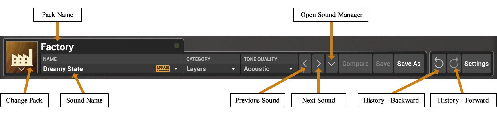
The utility section includes the top part of the sound manager which displays information on the currently selected sound and sound pack. This section also includes button to browse sounds and access to the Compare, Save, and Save As commands for sounds. For more information on sounds, sound packs, and the sound manager, please refer to Chapter 3.
The MIDI LED is located on the right of the sound name in the sound manager. The LED blinks when the synthesizer receives MIDI signal. If the application is not receiving MIDI signal, make sure that the host sequencer is sending MIDI to String Studio VS. If you are running in standalone mode, make sure that the MIDI controller you wish to use is well connected to your computer and that it is selected as explained in Chapter 7.
The History command allows one to go back through all the modifications that were carried out on sounds since the application was started. In order to travel back and forth in time, use the left and right-pointing curved arrows respectively. The application will switch between different successive states of the synthesizer.
The Compare button, located just before the Save button, is used to switch between Edit and Compare mode. This button is visible only once a modification is applied to a given program. It allows one to revert to the original version of a program in order to compare it with the current version. When in Compare mode, edition is blocked and it is therefore not possible to modify any parameter. The Compare mode must then be switched off by clicking on the Compare button in order to resume edition.
Clicking on the Settings button opens the settings window, which is where some general parameters of the synthesizer, such as tuning, number of polyphony voices, pitch bend range, and external modulator assignments, are fixed. For a detailed description of the different settings available, please refer to chapter 6.
The layer mixer, shown in Figure 35 includes general controls which can be applied to each layer. It is also where the output level of each layer and the master output is monitored and adjusted using the different level meters and Gain sliders.
Each layer can be named using a label. In order to edit a label, click on it and type on the computer keyboard. Once a name has been entered, hit the Return key or click outside the label in order to deselect this region.
A layer can be switched on or off by clicking on the power switch icon located just before its label. Switching off a layer not only mutes its output but completely deactivates the synthesis engine of the layer. Note that in this case, the split layer feature of the keyboard is also deactivated. Each layer can also be muted or soloed by using the M and S buttons respectively. The level of a layer is adjusted using the corresponding Gain slider. The volume is adjusted by click-holding the mouse on the cursor and moving it. A specific level can also be reached at once by clicking directly on the slider rail. Note that it is possible to move the cursor of both layer by the same amount. In order to move the sliders together shift-click on a slider and move it.
The Pan knob is used to position the output of a layer in stereo space by adjusting the relative amplitude of signals sent to the left and right channels. When in its leftmost position, signal is only sent to the left channel while in its rightmost position signal is only sent to the right channel. When in its center position, an equal amount of signal is sent to both channels.
Each layer can also be transposed independently using the Tune controls. The adjustments are relative to the general tuning of the synthesizer which is specified in the Settings window as explained above. This control is composed of two numbers separated by a dot. The first number indicates a value in semi-tones while the second one indicates a value in cents (one hundredth of a semi- tone). The amount of transposition can be adjusted by click-dragging upward or downward on the semi-tone and cent controls. Double clicking on these controls brings back their value to zero.
The level meters allow one to monitor peak and RMS (root means square) level of the left (L) and right (R) output channels from the synthesizer. As a limiter is located at the output of String Studio VS, it is important to make sure that the amplitude of the signal remains within values that ensure that no distortion is introduced in the signal at the output.
The optimal level for the signal lies in the light green zone of the level-meter (0 and +4 dBr) and should typically be reached when playing at mezzo forte (moderately loud) level. The 0 dB mark on the level meter has been adjusted to correspond to -20 dBFS (full scale). This means that at that level, the signal is -20 dB below the maximum allowed valuel. This ensures a headroom of 20 dB which should be more than enough to cover the dynamics of most playing situations and therefore guarantee that no additional distortion is added in the output signal.
A peak value mark allows one to follow the maximum level values reached by the output signal. The limiter is triggered when this mark enters the red zone of the level meter (17 dB) and it remains active while the side vertical bars at the top of the lever meter are switched on.
Clicking the gear icon next to the preset display at the top of the interface opens the Settings window (shown in Figure 25). This is where you can configure general parameters of the synthesizer, such as tuning, number of polyphonic voices, pitch bend range, and MIDI assignments. The Settings are organized into five sections, General, MIDI, MIDI Links, Hardware, and About, which can be accessed by clicking on the tabs on the left side of the window.
These settings are global—they are not saved with individual presets and therefore apply to all sounds. In other words, they remain unchanged when a new preset is loaded.

The size of the interface can be adjusted using the Display Zoom drop-down menu. A range of size ratios is available, from small to very large.
You can also resize the interface by clicking and dragging the lower right corner of the window.
The Voices setting allows you to adjust the number of polyphony voices used by String Studio VS-3. Click on the control and select the desired number of voices from the list.
In general, a higher number of voices is desirable for complex or layered playing. However, keep in mind that CPU usage increases proportionally with the number of active voices.
The Priority setting sets the behaviour of the keyboard when several notes are depressed at the same time when the Keyboard module is set to monophonic mode or when the maximum number of polyphonic voices has been reached in polyphonic mode. In monophonic mode, the Priority determines which of the lower, last, or higher note has precedence when several notes are played. In polyphonic mode, this control determines which of the lowest, highest, or oldest note is muted in order to replace it with the newest note played once the maximum of polyphonic voices has been reached. Note that since this parameter determines the note priority, the stolen note will be the opposite of what appears in the control display.
Musical instruments are typically tuned based on a fixed reference note (such as A440) and a temperament system. The reference note is a specific note with a fixed frequency—commonly 440 Hz for the A above middle C (A4). A temperament is a system of tuning that defines how the octave is divided and determines the frequencies of all other notes in a scale.
By default, String Studio VS-3 uses equal temperament and a frequency of 440 Hz for A4 (MIDI note 69).
You can transpose the instrument—shifting the pitch of all notes—by adjusting the Frequency value (in Hertz) of the selected reference note. Additionally, you can choose a different Reference Note from the drop-down menu. When a new note is selected, the Frequency parameter automatically updates to reflect its default tuning under A440 and equal temperament.
An interesting feature of String Studio VS-3 is its ability to use microtonal tunings based on different temperaments through Scala micro-tuning files.
To load a temperament file, open the Tuning drop-down menu, which displays a list of available temperaments. By default, only the Stretched Electric Piano Equal Temperament options are available. Additional temperaments can be added by clicking the Show Tuning Files button and copying your Scala files into the folder that opens.
Once a Scala file is selected from the Tuning menu, String Studio VS-3 will automatically load the corresponding temperament.
The Reference Note and Frequency settings in the Master Tuning section (explained above) are used to define the base note and its frequency for the selected Scala scale.
Changes made in the Settings window are applied globally to the synthesizer, regardless of the sound currently loaded.
In plug-in mode, settings are automatically saved with your DAW project, meaning they will be recalled the next time the project is opened.
To save your current settings as the default configuration, click the Save Current as Default button. These saved defaults will be used the next time you open a new instance of String Studio VS-3 in plug-in mode.
To revert to your default settings at any time, click the Load Default button—this is particularly useful when experimenting with changes and wanting to return to your preferred setup.
If needed, you can also restore the factory settings by clicking the Reset to Factory button.
In standalone mode, the program automatically reloads the last used settings from when it was last closed.
String Studio VS-3 responds to MIDI Program Change messages. To turn on/off this feature, simply check or uncheck the Enable option.
When enabled, String Studio VS-3 will load the sound from the currently selected sound pack whose index number matches the value received in the Program Change message.
If you prefer the software not to respond to Program Change messages, simply uncheck the Enable Program Changes option.
String Studio VS reacts to the MIDI pitch bend signal received by String Studio VS. The pitch bend wheel on the interface, located just below the Clock module on the Play panel, can also be used to modify the pitch of a sound. In order to adjust the range of the pitch bend, use the Pitch Bend Range drop-down menu. The different options are listed in number of semi-tones. Note that by choosing a value of zero semi-tone, String Studio VS will stop responding to MIDI pitch bend signal.
For more information on pitch bend, please refer to section 7.2.6.
The gain level of the signal—before the multi-effects processor—can be controlled via a MIDI controller, such as an expression pedal.
To turn on/off this feature, simply check or uncheck the Enable option.
By default, the MIDI Channel Volume controller is assigned to control this parameter. However, you can assign other MIDI Continuous Controllers (CCs) to this function.
To change the assignment:
The gain level of the signal—after the multi-effects processor—can be controlled via a MIDI controller, such as an expression pedal.
To turn on/off this feature, simply check or uncheck the Enable option.
By default, the MIDI Channel Volume controller is assigned to control this parameter. However, you can assign other MIDI Continuous Controllers (CCs) to this function.
To change the assignment:
The Macros settings is used to assign an external MIDI continuous controller to the Modulator1 and Modulator 2 modules used in each layer. One can select a specific controler from the list of controller numbers appearing when clicking on the drop-down menus of this section. The Learn command can also be used to assign a controller. When one of the Learn buttons is switched on, the corresponding modulator will be assigned to the first continuous controller from which a message is received. Note that when the None option is chosen, the corresponding Modulator will not respond to any controller.
For more information on the Modulator modules, please refer to section 4.2.5.
Any control on the String Studio VS-3 interface can be manipulated by an external MIDI controller through a MIDI Control Change assignment or MIDI link.
The list of currently active MIDI links appears in the Assignments table, each row in this table corresponds to a specific MIDI link. For each MIDI link, the following information is displayed: name of the linked parameter, the module it belongs to, the number of the MIDI cc linked to the parameter, and a minimum and maximum value for the parameter if set.
A specific configuration of assignments can be saved as a preset by clicking the Save button. This will open the MIDI Links Preset window which will prompt you to enter a name for the preset. A saved map can be loaded by clicking the Load button. The possibility to load and save assignment maps is convenient if you wish to create different maps for different controllers.
The Clear button can be used to disable all MIDI control assignments at once.
For more details on MIDI Control Assignments, please refer to Section 7.2.3.
This section lets you choose an audio output device from those available on your system. Multi-channel interfaces will have their outputs listed as stereo pairs.
On Windows, the audio output list is organized by driver type. Begin by selecting a type from the Audio Device Type drop-down menu. If available, ASIO drivers should be selected for optimal performance. The Configure Audio Device button lets you launch the manufacturer’s control panel for the selected device, if one is available.
After selecting an audio device, you can specify a sampling rate and buffer size from the options supported by your interface.
At the bottom of the window, you’ll find the list of available MIDI input devices. To activate an input, simply check the box next to the desired device. In standalone mode, it is possible to select the active MIDI channel using the Channel drop-down list.
For more details on audio and MIDI configuration, please refer to Chapter 7.
This section includes useful information such as:
It also includes a link to the PDF version of this manual.
This chapter explains how to select and configure Audio and MIDI devices used by String Studio VS. Audio and MIDI configuration tools are accessed by clicking on the Setting button located in the upper right corner of the String Studio VS interface and then the Hardware tab.
Note that in plug-in mode the audio and MIDI inputs, sampling rate, and buffer size are set by the host sequencer.
The hardware tab in the Settings window first allows you to select an audio output device from those available on your computer. Multi-channel interfaces will have their outputs listed as stereo pairs.
On Windows, the audio output list is organized by driver type. The device type is first selected from the Audio Device Type drop-down list. If you have ASIO drivers available, these should be selected for optimum performance. The Configure Audio Device button allows you to open the manufacturer’s setup program for your audio interface when available.
Once the audio input has been selected, you can then select a sampling rate and a buffer size from those offered by your audio interface.
The latency is the time delay between the moment you send a control signal to your computer (for example when you hit a key on your MIDI keyboard) and the moment when you hear the effect. Roughly, the latency will be equal to the duration of the buffers used by the application and the sound card to play audio and MIDI. To calculate the total time required to play a buffer, just divide the number of samples per buffer by the sampling frequency. For example, 256 samples played at 48 kHz represent a time of 5.3 ms. Doubling the number of samples and keeping the sampling frequency constant will double this time while changing the sampling frequency to 96 kHz and keeping the buffer size constant will reduce the latency to 2.7 ms.
It is of course desirable to have as little latency as possible. String Studio VS however requires a certain amount of time to be able to calculate sound samples in a continuous manner. This time depends on the power of the computer used, the preset played, the sampling rate, and the number of voices of polyphony used. Note that it will literally take twice as much CPU power to process audio at a sampling rate of 96 kHz as it would to process the same data at 48 kHz, simply because it is necessary to calculate twice as many samples in the same amount of time.
Depending on your machine you should choose, for a given sampling frequency, the smallest buffer size that allows you to keep real-time for a reasonable number of voices of polyphony.
The list of available MIDI inputs appears at the bottom of the Audio Setup dialog. Click on the Audio Setup button located in the lower left corner of the String Studio VS interface and then click on the checkbox corresponding to any of the inputs you wish to use.
The MIDI channel volume and expression controller (MIDI CC number 7 and 11 respectively) messages received by String Studio VS can be used to control gain parameters, and therefore the output volume, just before the multi-effects processor of each layer and after the global multi-effects processor. These controllers are enabled in the MIDI Control section of the Settings window which is opened by clicking on the Settings button located in the right of the utility section at the top of the interface.
The expression controller is set by default to control the gain parameter located before the multi-effects processor of each layer. This could be used, for example, to control the output volume of the synthesizer, but without loosing the tail signal from a reverb. In order to enable this controller, click on the Pre-Effects Output Gain option.
The channel volume controller is set by default to control the gain parameter located after the global multi-effects processor. In order to enable this controller, click on the Post-Effects Output Gain option.
Both the Pre and Post-effects gains can be assigned to other controllers. In order to change the assignment, use the drop-down menu corresponding to these gains to choose another MIDI continuous controller. Alternatively one can click on one of the Learn buttons which will link the corresponding gain parameter to the controller sending the next MIDI CC message received by String Studio VS.
Every control on the String Studio VS interface can be manipulated by an external MIDI controller through MIDI control change assignments or MIDI links.
In order to create a MIDI control assignment:
To deactivate a MIDI assignment, simply right-click/Control-click on the corresponding control on the String Studio VS interface and select the Forget MIDI Assignment command.
Note that MIDI assignments are not saved with sound presets. They are global parameters which apply to all sounds. When String Studio VS is used in plug-in mode, these assignments are saved with the DAW project and are therefore loaded when the project is opened. It is therefore possible to use different assignments in different projects.
In order to save the current configuration of assignments as the default map, open the Settings window by clicking on the Setting button located in the top right of the interface and use the Save Current as Default command in the MIDI Control Assigment section. This default map will be loaded the next time the program is started as a plug-in. In order to revert to the default map, after making some modifications for example, use the Load Default command in the Settings window. The Clear command is used to disable all MIDI control assignments at once.
String Studio VS responds to MIDI program change messages. In order to enable MIDI program changes, open the the Settings window by clicking on the Settings button in the top right of the interface and check the Enable Program Changes option in the MIDI Program section. When this is the case, String Studio VS loads the sound in the currently selected sound pack whose index number corresponds to the one received in the program change message. If you do not wish String Studio VS to respond to MIDI program changes, deselect the Enable Program Changes option.
String Studio VS reacts to the MIDI pitch bend signal received by String Studio VS. The pitch bend wheel on the interface, located just below the Clock module on the Play panel, can also be used to modify the pitch of a sound. The range of the pitch bend is 2 semi-tones up or down by default but can be changed. To adjust the range of the pitch bend, open the the Settings window by clicking on the Settings button in the top right of the interface and use the Pitch Bend Range drop-down menu. The different options are listed in number of in semi-tones. Note that by choosing a value of zero semi-tone, String Studio VS will stop responding to MIDI pitch bend signal.
Pitch bend can quickly be disabled for each layer from the Layer Settings window which is opened by clicking on the gear icon located next to the Split button in the lower left corner of the Play panel. In order to deactivate pitch bend for a givent layer, click on the Pitch Bend button under Layer A or B. Pitch bend is reactivated by clicking again on the button. .
String Studio VS responds to the signal from the modulation wheel of MIDI keyboards (continuous controller number 1). By default, the Modulator 1 modules of the sounds from the factory library have been mapped to this controller and therefore react to the modulation wheel.
For more information on the Modulator modules, please refer to section 4.2.5.
By default, String Studio VS responds to MIDI sustain pedal messages (MIDI cc number 64). The sustain pedal can however be turned on or off independently for each layer by using the corresponding buttons in the Layer Settings window which is displayed by clicking on the small gear icon located on the right of the ribbon keyboard of the Play view.
String Studio VS is available in VST2, VST3, AAX and Audio Units formats and integrates seamlessly into the industry’s most popular multi-track recording and sequencing environments as a virtual instrument plug-in. String Studio VS works as any other plug-in in these environments so we recommend that you refer to your sequencer documentation in case you have problems running it as a plug-in. We review here some general points to keep in mind when using a plug-in version of String Studio VS.
When String Studio VS is used as a plug-in, the audio and MIDI ports, sampling rate, buffer size, and audio format are determined by the host sequencer.
String Studio VS supports automation functions of host sequencers. All parameters visible on the interface below the Utility section and related to the synthesis engine can be automatized, in other words parameters from the Layer Mixer, Play, Synth, and Effects views.
Multiple instances of String Studio VS can be launched simultaneously in a host sequencer.
MIDI program changes are supported in String Studio VS. When a MIDI program change is received by the application, the current sound used by the synthesis engine is changed to that having the same index, in the currently loaded pack, as that of the MIDI program change message.
In order to use MIDI program changes, make sure the Enable Program Changes option is selected in the Settings window as explained in section 5.4.
When saving a project in a host sequencer, the currently loaded sound is saved with the project in order to make sure that the instrument will be in the same state as when you saved the project when you re-open it. Note that packs are not saved with the project which implies that if you are using MIDI program changes in your project, you must make sure that the pack you are using in your project still exists on your disk when you reload the project. The sounds must also exist and be in the same order as when the project was saved.
Using a plug-in in a host sequencer requires CPU processing for both applications. The load on the CPU is even higher when multiple instances of a plug-in or numerous different plug-ins are used. To decrease CPU usage, remember that you can use the freeze or bounce to track functions of the host sequencer in order to render to audio the part played by a plug-in instead of recalculating it every time it is played.
IMPORTANT! CAREFULLY READ ALL THE TERMS AND CONDITIONS OF THIS AGREEMENT BEFORE OPENING THIS PACKAGE. OPENING THIS PACKAGE INDICATES YOUR ACCEPTANCE OF THESE TERMS AND CONDITIONS. IF YOU DO NOT AGREE WITH THE TERMS AND CONDITIONS OF THIS AGREEMENT, PROMPTLY RETURN THE UNOPENED PACKAGE AND ALL COMPONENTS THERETO TO THE PARTY FROM WHOM IT WAS ACQUIRED, FOR A FULL REFUND OF ANY CONSIDERATION PAID.
This software program, any printed materials, any on-line or electronic documentation, and any and all copies of such software program and materials (the “Software”) are the copyrighted work of Applied Acoustics Systems DVM Inc. (“AAS”), its subsidiaries, licensors and/or its suppliers.
Preparing your download…
This can take up to a minute.