Acoustic Object Synthesizer
Information in this manual is subject to change without notice and does not represent a commitment on the part of Applied Acoustics Systems DVM Inc. The software described in this manual is furnished under a license agreement. The software may be used only in accordance of the terms of this license agreement. It is against the law to copy this software on any medium except as specifically allowed in the license agreement. No part of this manual may be copied, photocopied, reproduced, translated, distributed or converted to any electronic or machine-readable form in whole or in part without prior written approval of Applied Acoustics Systems DVM Inc.
Copyright ©2017 Applied Acoustics Systems DVM Inc. All rights reserved. Printed in Canada.
Program Copyright ©2017 Applied Acoustics Systems, Inc. All right reserved.
Objeq is a Trademark of Applied Acoustics Systems DVM Inc. Windows and Windows Vista are registered trademarks of Microsoft Corporation. Mac OS and Audio Units are registered trademarks of Apple Corporation. VST Instruments and ASIO are trademarks of Steinberg Soft Und Hardware GmbH. RTAS and AAX are registered trademarks of Avid Technology Inc. All other product and company names are either trademarks or registered trademarks of their respective owner. Unauthorized copying, renting or lending of the software is strictly prohibited.
Visit Applied Acoustics Systems DVM Inc. on the World Wide Web at
Objeq Delay is a creative effect processor based on the combination of an acoustic filter and a delay unit. The input signal is first processed through acoustic resonators such as drumheads, strings, plates, and bars and a traditional filter module allowing to add acoustic resonances to the sound and change its timbre. The signal is then sent to a versatile stereo delay allowing for the creation of complex rhythmic patterns or echo effects.
Objeq Delay is entirely based on Applied Acoustics Systems (AAS) physical modeling technology and uses no sampling nor convolution algorithms. Sound is processed by solving, on the fly, mathematical equations modeling the different types of resonators and effect components.
Before discussing Objeq Delay in more detail, we would like to take this opportunity to thank you for choosing an AAS product. We sincerely hope that this product will bring you inspiration, pleasure and fulfill your creative needs.
The following minimum computer configuration is necessary to run Objeq Delay:
Installation and authorization of Objeq Delay is quick and easy. For the installation of our different products we use so-called custom installers which include both the program itself and your licence information. Installation and authorization can therefore be carried out automatically in a single step and from a single file when your computer is online. AAS products use a a copy protection system based on a a proprietary challenge/response key exchange and therefore their authorization does not rely on other third party software and/or hardware.
In order to start the installation process, simply double-click on the installer file that you have downloaded. This will first install the program and then use the licence information included in the custom installer file to to carry out automatically the challenge/response procedure.
Once the installation is completed, you can check your licence information by starting the program and clicking on the chevron icon at the top of the interface. This will open a dialog box in which you should see your serial number and the email address which you used in order to get the installer file. Note that your serial number is also sent to you by email when your custom installer is created.
If your computer is offline when running the installer, or if the authorization procedure could not be completed for another reason, the dialog box will will not show your serial number and you will be prompted to authorize the program. In that case, click on the Authorize button and follow the on-screen instructions. Note that it is possible to use the program during 15 days before completing the authorization process. After that period, the program will not function unless it is authorized.
Objeq Delay integrates seamlessly into the industry’s most popular multi-track recording and sequencing environments as a stereo effect plug-in. Objeq Delay works as any other plug-in in these environments so we recommend that you refer to your sequencer documentation in case you have problems running Objeq Delay as a plug-in.
The About box is opened by clicking on the chevrons located at the very top of the interface. The box is closed by clicking again on the chevrons or outside the box. Useful information is displayed in this box such as the program’s version number, the serial number that was used for the authorization and the the email address that was used for registration. The box also includes a link to the pdf version of this manual.
AAS technical support representatives are on hand from Monday to Friday, 10am to 6pm EST. Whether you have a question on Objeq Delay, or need a hand getting it up and running as a plug-in in your favorite sequencer, we are here to help. Contact us by phone or email at:
Our online support pages contain downloads of the most recent product updates, and answers to frequently asked questions on all AAS products. The support pages are located at:
Throughout this manual, the following conventions are used:
Objeq Delay is an effect processor built around the combination of a filter, acoustic resonators and a delay module. Objeq Delay can both transform the timbre of the incoming signal and create rhythmic effects and/or add echoes to the signal.
The general signal flow is illustrated in figure 1 and follows the general layout of the interface. The signal is first sent through a low-pass and a high-pass filter followed by an acoustic resonator. This first stage allows one to adjust the low and high frequency content of the tone and add resonances associated with different types of acoustic objects. Available resonator types are: string, plate, drumhead, and beam. The characteristics of these resonators are easily adjustable for a great range of tones.
The transformed signal is then sent to a pre-delay followed by a second delay with feedback loop. These delays, which can be used in different configurations and will be reviewed in detail in Section 4.5, are used to create rhythmic effects and add echoes to the signal.
The patch also includes an LFO module for the modulation of the different filter, resonator, and delay parameters. Finally, a Mixer modules allows one to control the amount of dry and wet signal in the output signal as well as to control its general output level.
Objeq Delay comes with several factory presets, called programs, covering a wide range of effects. This collection of programs lets you play and familiarize yourself with this effect processor without having to tweak a single knob. Soon, however, you will be experimenting and creating your own sounds and projects that you will need to archive or exchange with other users. In this section, we review the management of programs.
Presets are stored in banks contaning so-called programs. The name of the currently selected bank is shown in the Bank drop-down display located in the top of the Objeq Delay interface. The list of available banks is viewed by clicking on the Bank display. A bank can be selected by navigating in the list of banks using the left and right-pointing arrows in the display or by clicking on its name when the list of banks is open. Clicking on the bank display brings focus on this section of the interface, the display is then outlined by an orange line, and one can then navigate through the list of banks using the up, down, left, or right arrows of the computer keyboard.
The list of programs included in the currently selected bank can be viewed by clicking on the Program display located below the Bank display. A program is selected by using the left and right-pointing arrows or by clicking directly on its name. Once a program is selected, the value of the different parameters of the synthesizer are updated and it can then be played. As for the bank list, one can navigate through the program list using the computer arrows after clicking on the Program display.
Programs are saved by clicking on the Save button located to the right of the Program display. When a program has just been loaded, this command is greyed and therefore inactive. It is activated as soon as a parameter of the interface is modified. Clicking on this command replaces the stored version of the program with the new one.
The Save As command is activated by clicking on the corresponding button which opens the Save Program pop-up window. It is then possible to save the program under a new name or its current one in any of the available program banks. Note that if the original name of the program is used, a new program with the same name will be created at the end of the program list meaning that the original program is not erased. This also implies that it is possible to have many programs with the same name in the same bank.
Banks and Programs can be organised using the Bank Manager. The manager window is displayed by clicking on the Manager button located to the right of the Bank and Program display. It is closed by clicking again on the same button. On the left of the window, one finds the list of banks. Clicking on a bank name fills the list of programs located in the center of the window with the name of these included in the selected bank.
A new bank can be created by clicking on the + button below the bank list. This opens the Create New Bank window in which the name of the new bank can be entered. A bank can be deleted by first selecting it in the bank list and then clicking on the - button. Be careful, this command erases a bank and all the programs it contains; this operation is permanent and can not be undone. In order to rename a bank, simply click on the Rename button and enter a new name.
Banks and the information corresponding to each of its programs is stored in a simple text file on your computer hard disk. In order to view these bank files, click on the Show Files button under the bank list. On Windows, this command will open an Explorer window at the location where the files are stored. On Mac OSX, the command has a similar effect and opens a Finder window. All the bank file names follow the same format and begin with the bank name. These files can be used for backups or to exchange presets with other users.
The list of programs included in the selected bank is displayed in the program list in the center of the manager window. Presets are selected by clicking on their name which updates the program information appearing on the right of the preset list. Program information includes the name of the preset, its author and comments. This information can be updated by clicking on the corresponding box which opens an edition window. Note that multiple presets can be updated simultaneously by selecting more than one preset at once and clicking on a preset information box.
A multiple selection consisting of adjacent programs is obtained by holding down the Shift key on the computer keyboard and then clicking on the name of the first program to be copied and then the last one. A non-adjacent multiple selection is obtained by holding down the Ctrl/command computer key and clicking on the name of the different programs to be copied. It is also possible to select all programs at once by clicking on the Select All button at the bottom of the program list.
Programs can be copied to another bank by clicking on the Copy button. A program must first be selected by clicking on its name on the program list; it is then copied by moving the mouse to a given bank in the Bank list on the right and clicking on the bank name. The Move command is activated by clicking on the Move button; it copies a preset to a new bank but also erases it in the original bank. A multiple selection of programs can be used with the Copy and Move commands
Programs can be deleted from a bank by first selecting them and then clicking on the Delete button. This will move the programs to a special bank called Trash which is located below the regular list of banks. This means that deleted programs can always be recuperated as long as they are not deleted from the Trash bank. The content of the Trash bank is viewed by clicking on its name; the different programs can then be moved to the other banks as explained above. The Trash bank can be emptied by clicking on the Empty Trash button which appears below the program list when the Trash bank is selected. Be careful as this command can not be undone.
User banks are stored on disk as simple text files located in the following folders:
On Mac OS:
/Users/[user name]/Library/Application Support/Applied Acoustics Systems/Objeq Delay/Banks
On Windows:
%AppData%\Applied Acoustics Systems\Objeq Delay\Banks
The bank files saved by Objeq Delay are named using the following convention:
[name of bank].Objeq Delay Bank
These files contain all the information corresponding to the programs they include. These files can be displayed directly from Objeq Delay by opening the Bank manager and clicking on the Show Files button. This will open an Explorer or Finder window on Windows or Mac OS respectively at the right location.
The simplest way to create a backup of banks and programs is to make a copy on an external media of the above mentioned folders. Individual banks can be backed-up by making copies of individual bank files.
Banks and programs can easily be shared with other Objeq Delay users. This operation simply involves the exchange of the above mentioned user bank files. When a new bank file is copied to the bank folder, it is automatically available to Objeq Delay.
Note that individual programs can not be exported. They always appear inside a bank file. If you only wish to share a few programs, create a new bank, copy the programs you wish to exchange to this bank and share the corresponding bank file.
If necessary, it is possible to restore the original factory library of banks and programs. The original factory bank files are located in the following folders:
On Windows 64-bit:
C:\Program Files (x86)\Applied Acoustics Systems\Objeq Delay\Factory Library
On Windows 32-bit:
C:\Program Files\Applied Acoustics Systems\Objeq Delay\Factory Library
On Mac OS startup disk:
/Library/Application Support/Applied Acoustics Systems/Objeq Delay/Factory Library
Restoring the factory library simply involves copying the files contained in these folders and pasting them in the user bank folders listed in Section 3.4. The user bank folders can be opened directly in an Explorer or Finder window, on Windows and Mac OS respectively, or by using the Show Files command directly from the Objeq Delay bank manager.
Note that if you have bank files with the original factory bank names in your user bank folder, they will be replaced by the original factory files. This means that you will lose programs that you would have modified or created in these banks. This operation must therefore be done with caution and it is recommended that you make copies or rename your user banks before proceeding with the restore.
The History control, is located to the right of the Program display, allows one to go back through all the modifications that were made to programs since the application was started. In order to travel back and forth in time, use the left and right-pointing arrows respectively. The application will switch between different program states and indicate the time at which they were modified.
The Compare button, located to the right of the History control, is used to switch between Edit and Compare mode. This button is visible only once a modification is applied to a given program. It allows one to revert to the original version of a program in order to compare it with the current version. When in Compare mode, edition is blocked and it is therefore not possible to modify any parameter. The Compare mode must then be switched off by clicking on the Compare button in order to resume edition.
This section can be used as a reference for the different controls appearing on the Objeq Delay graphical interface. We begin by describing the behavior of the different types of controls appearing on the interface and then describe the parameters of each module of the synthesizer.
The different parameters of this effect are adjusted using controls such as knobs, switches and numerical displays. A specific control is selected by clicking on it. A coarse adjustment is obtained by click-holding the parameter and moving the mouse, or the finger on a track pad, either upwards and downwards or leftwards and rightwards. The value of the parameter replaces its label while it is being adjusted.
Fine adjustment of a control is obtained by holding down a modifier key of the computer keyboard (Shift, Ctrl, Command or Alt key) while adjusting the parameter. Precise values can also be entered manually by clicking on the parameter label and typing the value on the computer keyboard.
Double clicking on a knob brings it back to its default value when available.
Switches are turned on or off by clicking on them. They are used to activate or deactivate modules and other parameters such as the sync feature.
Some displays reveal a drop-down menu when clicking on them. Adjustment of the control is obtained by clicking on a selection.
Most parameters of Objeq Delay can be modulated with the signal from the LFO module as will be explained in section 4.6. Automation can also be used to modify the value of the different parameters in time. This can be useful when the LFO module is already used to modulate a specific parameter.
The rate of certain effect parameters can be synchronized to the clock of a host sequencer. To do so, simply turn on their Sync switch.
Synchronisation values range from a half note (1/2) to a sixteenth note (1/16) where the duration of the quarter note is determined by the host sequencer. The LFO module can also be synced to a triplet (t) or a dotted note (d). Sync values can be adjusted with the corresponding parameter knob or by clicking on the # symbol to the right of the knob which reveals a display with the different possible sync values. The desired parameter rate is adjusted by clicking on one of the note values.
The sync display also includes a Multiply parameter providing another way to modify the rate of parameter. When the Sync button is switched on, this parameter applies a multiplication factor to the current synchronisation value which can take one of five different values betwen 1/2 and 2:
When the Sync button is switched off, the multiplication factor is applied to the value of the parameter as determined by corresponding knob position. Note that the value of the Multiply factor always appears to the left of the parameter knob. This is useful when the Sync display is not apparent.
This Multiply parameter has two main uses. It can first be mapped to an automation parameter of the host sequencer in order to switch rapidly between musically interesting parameter rates. It can also be used to obtain synchronisation values not appearing in the Sync display. For example a Multiply value corresponding to a whole note is obtained by choosing a half note on the note display and a Multiply factor of 2. A thirty-second note is obtained by choosing a sixteenth note on the display and a Multiply factor of 1/2.
The size of the graphical interface can be adjusted by click-dragging the handle in its lower right corner. While resizing the interface the zoom factor is displayed in the upper left corner of the interface. This zoom factor can always be displayed by positioning the mouse on this corner. When clicking on the zoom factor, a drop-down menu with specific size ratios is displayed. Selecting a value resizes the interface automatically to that ratio. Note that this resize feature is only available for 64-bit versions of the program.
Exciting an object such as the skin of a drum by hitting it with a mallet results in a complex vibrational motion. It is this vibration of the object that will create pressure waves in the surrounding air which will propagate to our ears as sound waves. In Objeq Delay, the input signal is used to excite different kind of acoustic objects. In other words, we listen to the signal through the object or as if it was filtered by its natural resonances.
Mathematically, a complex vibrational motion can be decomposed into elementary motion patterns called the normal modes of the object. Under a normal mode, all the parts of the structure move in phase and at the same frequency in a sinusoidal motion. In other words, this complex motion results from the fact that objects naturally oscillate at many different frequencies at once, each frequency being related to a normal mode of vibration. These frequencies are called partials; the lowest partial is called the fundamental and the higher ones are referred to as overtones. When relating to music, the fundamental corresponds to the note played and the overtones are called harmonics as in most musical instruments their frequency is a multiple integer (or almost) of the fundamental.
As an example, the vibration motion associated with two normal modes of a rectangular plate is illustrated in Figures 3 and 4. In the first figure, one can see the vibration motion associated with two different normal modes of the plate (modes [1,1] and [3,2]). Over one period of oscillation, all the points go up and down in phase. Figure 4 is a top view of the plate and shows contour lines corresponding to the same normal modes. A contour line groups points that oscillate with the same amplitude. In particular, the straight lines in the second graph of this figure, corresponds to so-called nodal lines where the amplitude of the motion is zero and therefore where the plate is still.
The principle remains the same for all mode, the motion pattern only becoming more and more complex as the order of the mode increases. The full motion of a plate or any other object, however complicated, will always correspond to a combination of all its normal modes resulting in a frequency response specific to each object. Figure 5 shows one such frequency response for a plate object. This can be viewed as the frequency response of the filter through which the input signal will be filtered by Objeq Delay. Of course, this frequency response will be different for every type of object and will vary depending on the specific settings of its parameters.
The relative frequencies or ratio of the frequency of the overtones to the fundamental frequency is specific to the type of the object and its boundary conditions (whether its boundaries are free to vibrate or are fixed). In other words this distribution of partials is characteristic of the type of object and could be viewed as its tonal signature; it allows us to distinguish, for example, a vibrating plate from a drumhead. The specific frequency of the partials, related to the sensation of pitch, is determined by the dimensions of the object, for example a small plate will have a higher pitch than a larger one.
But this is not all, we can distinguish different types of objects, such as a vibrating plate and a beam, but also two objects of the same type but made out of different material. For example a metal plate will sound brighter and have a longer decay than a wooden plate. This is due to the fact that the physical properties of an object depend on its material which determine the relative amplitude and phase of the different partials as well as their damping, a measure of how fast they will decay once excited. The specific amplitude, phase and damping of each partial therefore determine the specific tone of the object as well as how it evolves with time.
There is finally one more parameter which affects how an object sounds, it is the point of excitation. Indeed, a drumhead does not sound the same if it is hit in the middle or near the rim of the drum. This can be understood by the fact that exciting an object on a point located on a nodal line of a mode (a line where amplitude of the motion associated with a mode is zero) does not allow the transfer energy to that specific mode and its corresponding partial will not be excited. The effect will not be as pronounced but will still exist as the excitation point is moved around the nodal lines which explains how the excitation point influences the relative amplitude of the partials and therefore the tone.

The Object module is used to filter the input signal through acoustic resonators in order to change their tonal color as explained in the preceding section. A wide variety of effects can be obtained by changing the type of objects and their characteristics.
The Object selector allows one to choose the type of resonator used. The object type can be changed by clicking on the object icons or by using the drop-down menu at the top of the icon display. The list of objects include
The reference pitch of an object, or in other words the frequency of its first partial or resonance frequency, is adjusted using the Frequency parameter. This parameter, related to the size of the object, can vary between 20 Hz and 4 kHz.
The decay time of the partials of the object is determined by the Decay knob. Turning this knob clockwise increases the decay time of the object resonances.
The Material control allows one to fix the decay time of partials as a function of frequency with respect to that of the fundamental. This is a parameter characteristic of the material of the object. In its leftmost position, the decay time of low partials is longer than that of high partials. Turning the knob clockwise increases the decay time of the higher frequencies resulting in a more metallic sound.
The Formant parameter is used to control where the excitation signal is applied on a resonator. This is an important parameter as it affects the relative amplitude of the different partials of the resonator and therefore the spectrum of the sound it radiates as explained in Section 4.2.1. This position is indicated as a percentage of the total size of the object. The minimum value of the control corresponds to an excitation applied on the border of the object while the maximum value corresponds to an excitation applied at its center.
The Object module transforms the tone of input signal. We give here a few examples of how the different parameters of this module can be used to obtain specific effects.
The Object module can transform percussive sounds such as kicks and snares in many interesting ways. When the Frequency parameter is tuned to the fundamental frequency of the original sound, the object reacts strongly to the input signal and mixing both adds resonance or body to the input signal.
Increasing the Decay time of the resonator can be used to increase the duration of the sound and add a release phase which was not present in the original signal. A variation of this technique consists in tuning the resonator to an harmonic of the original sound which will enhance it with higher frequencies.
Of course, it is also possible to tune the resonator to a frequency not necessarily related to the input signal. This will add frequency content not present in the original sound. This can be used to transform completely the original sound by listening only to the wet signal (see Mixer module in Section 4.7). In that case, the input signal is simply used as a trigger for the resonators.
Note that finer control of the tone is obtained when using these techniques in conjunction with the First delay line of the Delay module (see Section 4.5). Indeed, using a very short pre-delay can be used to slightly desynchronize the dry and wet signals. In the case of a percussive sound, this can be used to leave the original attack unchanged while adding some resonance or a release phase to the signal. For this type of use, the Feedback parameter of the Delay module must be set to zero in order to avoid echoes in the signal.
The resonators in the Object module are basically filters and can as such be used in any situation where a traditional filter would be used. For example a bandpass filter on a synth sound, a low-pass filter on a DJ console, or a wah on a guitar sound. The filtering effect from these resonators is very rich and therefore the potential for enhancing or transforming a sound or loop is enormous.

In addition to the acoustic filtering from the Object module, the tone of the input signal can be modified using a Low Cut and High Cut filter. The cut-off frequency of each of these filters can be adjusted to a value between 20 Hz and 20 kHz using the High Cut and Low Cut knobs. The steepness of the frequency response of these filters can be adjusted using the Poles parameter which can be set to a value of 1, 2, or 4 corresponding to a first order (-6dB/octave), second order (-12 dB/octave), or fourth order (-24 dB/octave) filter respectively.
This filter is useful to control how the object reacts to the input signal providing additional tonal control. The filter limits the amplitude of low and high frequencies in the source signal sent to the object and therefore the ability of the signal to excite the resonator at these frequencies. For example, turning the Low Cut knob clockwise increases the cut-off frequency of the low-cut filter and therefore reduces the vibration of the object at low frequencies resulting in a less boomy sound. Turning the knob further will make the object sound more and more metallic because its spectrum then becomes dominated by high frequencies.
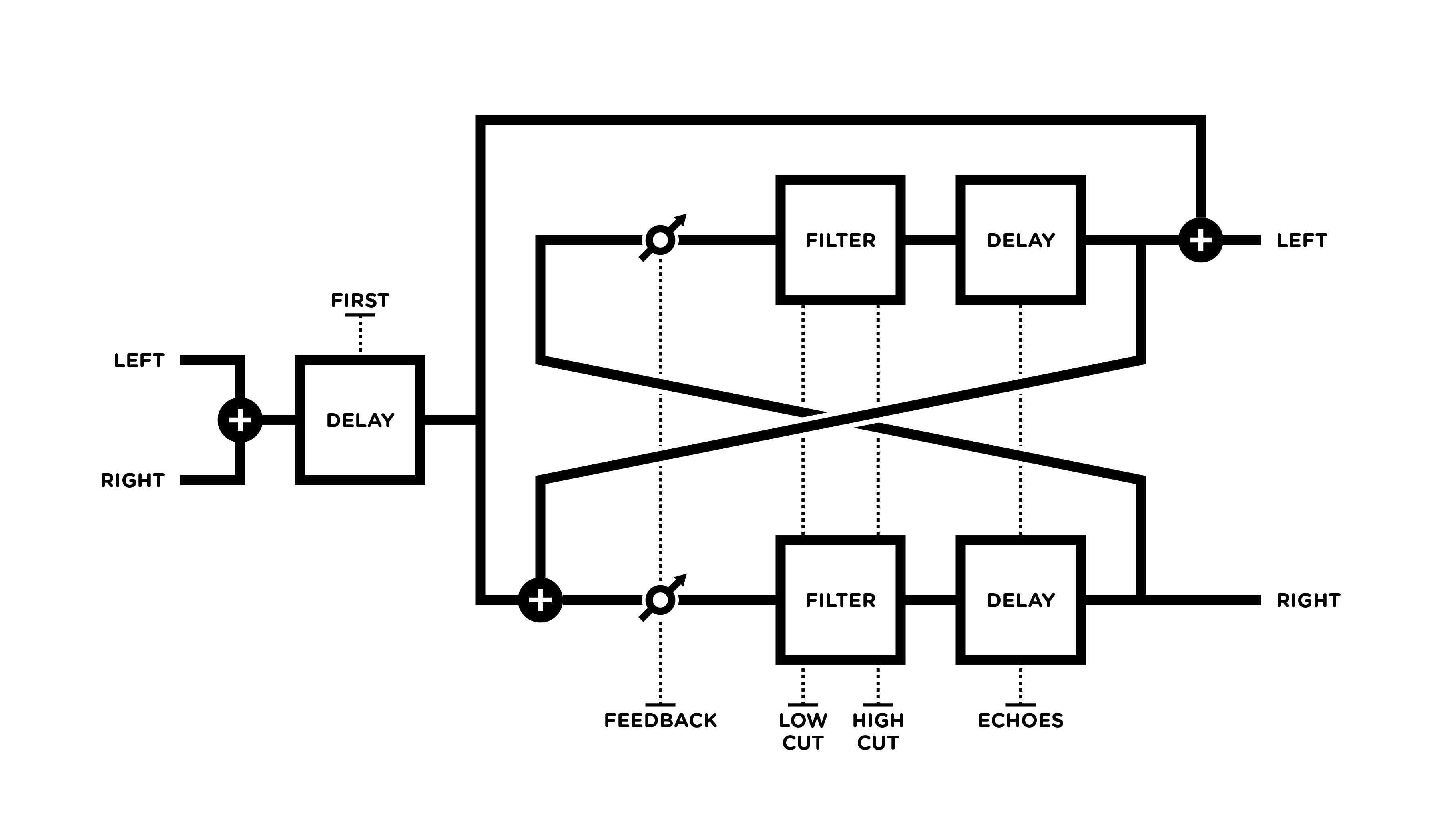
The Delay module has two channels (left and right) each with two delay lines as shown in Figure 6. The first line applied a simple delay to the input signal while the second line is in fact a feedback loop allowing for echoes. Each of these delay lines can be adjusted independently allowing for creative rhythmic effects. The duration of the initial delay is adjusted using the First knob while that of the second one is adjusted using the Echoes knob.

The delay time can be adjusted to specific values but it can also be synced to the tempo of the host sequencer. When the Sync controlled is not activated, the value of this parameter is displayed in seconds and it is adjusted using the First or Echoes knob.
When the Sync button is switched on, the value of the delay is synced to the tempo of the host sequencer as explained in Section 4.1.5. Sync values can be adjusted with the First or Echoes knobs or by clicking on the # symbol to the right of the knobs. In the latter case, a display appears with the different possible sync values and the Rate parameter is adjusted by clicking on one of the note values.
The second delay line is part of a feedback loop allowing one to create echo effects. The loop includes a Feedback knob which applies a gain coefficient to the signal before it is injected back into the delay line. The gain coefficient is displayed in dB and ranges from -∞ in its leftmost position to a value of 0 dB in its rightmost position. When this parameter has a value of -∞, the signal is multiplied by a value or zero which means that no signal is injected back in the loop. In its rightmost position, the signal is multiplied by a value of one which means that the signal is sent back into the loop with no attenuation. Intermediate values allow one to adjust the decay rate of the echoes.
The loop also includes a 6 dB/octave low cut and high cut filter. The cut-off frequency of these filters is adjusted using the Low Cut and High Cut sliders respectively allowing one to control the frequency content of the echoes. Note that the filters have no effect when the Feedback parameter has a value of -∞ (leftmost position).
The Link parameter is used to link the values of the First and Echoes knobs, in other words to adjust the duration of all delay lines of the module to the same value. The value of the delay is then adjusted by turning the First or Echoes knob which turn together. This parameter is switched on and off by clicking on the control label or LED. This is useful when one wants the duration of the echoes to have the same duration as that of the first delay.
The Delay can be used in ping pong mode by switching on the Ping Pong switch. In this mode, the left and right channels of the input signal are mixed together and then go through the First delay line of the left channel. The signal then alternates between the right and left Echoes delay line as shown in Figure 7.
Very different kind of effects can be obtained with the Delay module depending on its settings. We describe here a few typical uses of this module.
A short single-repeat echo effect, or slapback effect, is obtained by setting the Feedback parameter to a value of -∞, thereby disabling the second delay line of each channel of the module. The slapback time is then controlled with the First knob.
Contrary to a traditional delay module, Objeq Delay can modify the tone of the input signal before sending it into the delay lines. In other words, the Filter and Object modules act apply a filtering effect on the input signal. It can be interesting to use this new signal without initial delay and with echoes or not. In the case when one wants only to hear the filtering effect and eventually echoes:
It is a frequent practice to play ghost notes between beats. If the source is a simple rhythm, the delay effect can be used to add ghost notes by using two different synchronisation values for the the First and Echoes delays.
For example, with a snare drum on the second and fourth beats, one could adjust the sync value of the First delay to a value or 1/16 or 1/8D (a sixteenth note or a dotted eighth note) in order to delay the first ghost note between two eighth notes. The Echoes parameter is then synchronized to a value of 1/8 (eight note) so that each subsequent repetition falls between eighth notes. The Balance knob in the Mixer module is used to adjust the level of the ghost notes.
A comb filter effect is obtained by adding a delayed version of a signal to itself. This results in regularly spaced regions of constructive (peaks) and destructive interference (notches) in the spectrum hence the name. In order to obtain this effect:
Chorus and flanging effect are obtained in a way similar to the comb filtering effect except that the length of the delay line is modulated.
In general, the higher the value of the Rate parameter is the smaller the value of the Amount parameter must be. An LFO with a sinusoidal waveform, a relatively slow Rate value and relatively high value of the Amount parameter will sound like a flanger. Increasing the Rate value and decreasing the amplitude of the modulation will make the effect sound like a chorus.
The LFO module is used as a modulation source for the different modules of Objeq Delay.
The Rate parameter is used to control the rate or frequency of the LFO module. The rate can be adjusted manually but it can also be synced to the tempo of the host sequencer as explained in Section 4.1.5. When the Sync controlled is not activated, the value of this parameter is displayed in Hertz and it is adjusted using the Rate knob. When the Sync button is switched on, the value of the Rate parameter is synced to the tempo of the host sequencer and the parameter value is then displayed in note values. Sync values can be adjusted with the Rate knob or by clicking on the # symbol to the right of the Rate knob which might be convenient. In the latter case, a display appears with the different possible sync values and the Rate parameter is adjusted by clicking on one of the note values.
The sync display also includes a Multiply parameter providing another way to modify the Rate of the LFO. When the Sync button is switched off, the multiplication factor is applied to the frequency of the LFO in Hertz. Note that the Multiply factor always appear to the left of the Rate knob. This is useful when the Sync display is not apparent.

The type of waveform of the LFO is selected with the Type drop-down menu on the top of the module. The possible values for the waveforms are Sine, Triangular, Square, Random and Random Ramp. From these basic wave shapes a great range of different waveforms can be created with the use of the Phase and PW (pulse width) knobs as will be explained below.
These elementary waveforms are illustrated in Figure 8. Note that they are obtained when the Phase knobs is in its leftmost position (set to a value of 0%) while the PW knob is in its middle position (set to a value of 50%). The Random and Random Ramp waveforms are based on the Square and Triangle waveform respectively. In the case of the Random waveform the amplitude is set randomly at every change of value. In the case of the Random Ramp waveform, the peak and minimum values of the triangular waveform are changed randomly at every period of the waveform as illustrated in Figure 9.

The PW parameter is used to vary the time taken by the waveform to go from its peak value and reach its minimum value. This time is expressed in percentage of a period. When this knob is in its center position, this time is exactly half the oscillation period which means that the waveforms are perfectly symmetric as shown in Figure 8. Using a PW value smaller than 50% will compress the waveform in the first part of its period and will stretch it towards the end whereas a value greater than 50% will have an opposite effect as shown in Figure 10 for a square wave.
An interesting use of the PW parameter is to create a saw-tooth waveform from the triangle waveform. A ramp-up waveform is obtained by using a value PW value of 0% while a ramp-down waveform is obtained by using a value of 100% as shown in Figure 11.

The Phase parameter is used to adjust the starting point of the waveform. This start point is expressed in percentage of a period. When this parameter is in its leftmost position (a value of 0%) the waveform starts at its peak value which is assumed to be the zero phase position. Increasing the Phase parameter will displace the starting point to a later point of the waveform as illustrated in Figure 12.
The Destination drop-down display is used to choose which parameter of the effect will be modulated by the signal from the LFO module. The destination can be any of the main parameter of the different modules of the effect. The only destination option not corresponding to a control of the interface is the Wet VCA option. It is used to modulate the amplitude of the wet portion of the output signal of the effect while leaving that of the dry portion unchanged.
The Polarity parameter controls how the modulation signal is applied and modifies the value of the destination parameter. The Polarity has three different positions whose effects are illustrated in Figure 13. When the switch is in its middle position (±), the variation of the value of the destination parameter follows the modulation signal. When the value of the modulation signal is zero, the parameter value is equal to that specified by its corresponding knob. When the modulation signal is positive, its value increases while it decreases when the modulation signal becomes negative.
When this parameter is set to negative polarity (leftmost position), the value of the destination parameter varies in an opposite way to that of the modulation signal and is always reduced with respect to the setting of the corresponding knob. When the modulation signal reaches its minimum value, the value of the modulated parameter is equal to that specified by its knob. As the value of the modulation signal increases, the value of the destination parameter is reduced until it reaches its minimum value when the modulation signal is at a maximum.
When the Offset parameter is set to positive polarity (rightmost value), the value of the destination parameter is always increased from the value specified by the corresponding knob and follows the motion of the modulation signal. When the modulation signal is at a minimum, the value of the destination parameter is equal to that specified by its corresponding knob. The value of the modulated parameter then increases until it reaches a maximum when the modulation signal also reaches a maximum.
The Amount knob is used to adjust the amplitude of the modulation signal from the LFO module. The value of this parameter varies on a scale from 0 to 100% and the maximum value of the amplitude varies depending on the choice of the Destination parameter.
The Mixer module is used to adjust the output level of the effect as well as the mix of wet and dry signal in the output signal.

The Balance knob allows one to control the relative amount of wet and dry signal. In its middle position, there is an equal amount of wet and dry signal. Turning the knob anti-clockwise reduces the amount of wet signal in the mix while keeping the amount of dry signal unchanged. The amplitude of wet signal is gradually reduced as the knob is turned to the left until it reaches a value of zero in its leftmost position resulting in a mix with only dry signal. Starting from the middle position of the Balance knob and turning it clockwise has a similar effect but on the dry signal. As the knob is turned to the right, the amount of dry signal in the mix is reduced while keeping the level of wet signal unchanged. When the knob is in its rightmost position, there is no dry signal in the mix and the output signal only has wet signal.
The Output knob is the master level of the effect and controls the amplitude of the output signal from the effect. The level is displayed in dB and can vary from -∞ (no output signal) in its leftmost position to 20 dB in its rightmost position.
The Out/In switch is used to determine if the input signal is sent into the effect or not. In its left position (out), the input signal is sent directly to the output without going through the effect. When the switch is in its right position (in), the input signal is sent into the effect. Note that this switch is different from a bypass control. Indeed, if the effect is already active when the switch is turned to its out position, the input will be directed to the output but remaining echoes in the effect will be heard.
The level meter allows one to monitor peak and RMS (root means square) level of the left (L) and right (R) output channels from the synthesizer. As a limiter is located at the output of Objeq Delay, it is important to make sure that the amplitude of the signal remains within values that ensure that no distortion is introduced in the signal at the output.
The 0 dB mark on the level meter has been adjusted to correspond to -20 dBFS (full scale). This means that at that level, the signal is -20 dB below the maximum allowed value. This 0 dB level mark should typically correspond to playing at mezzo forte (moderately loud) level. This ensures a headroom of 20 dB which should be more than enough to cover the dynamics of most playing situations and therefore guarantee that no additional distortion is added in the output signal.
A peak value mark allows one to follow the maximum level values reached by the output signal. The limiter is triggered when this mark enters the red zone of the level meter (17 dB) and it remains active while the side vertical bars at the top of the lever meter are switched on.
IMPORTANT! CAREFULLY READ ALL THE TERMS AND CONDITIONS OF THIS AGREEMENT BEFORE OPENING THIS PACKAGE. OPENING THIS PACKAGE INDICATES YOUR ACCEPTANCE OF THESE TERMS AND CONDITIONS. IF YOU DO NOT AGREE WITH THE TERMS AND CONDITIONS OF THIS AGREEMENT, PROMPTLY RETURN THE UNOPENED PACKAGE AND ALL COMPONENTS THERETO TO THE PARTY FROM WHOM IT WAS ACQUIRED, FOR A FULL REFUND OF ANY CONSIDERATION PAID.
This software program, any printed materials, any on-line or electronic documentation, and any and all copies of such software program and materials (the “Software”) are the copyrighted work of Applied Acoustics Systems DVM Inc. (“AAS”), its subsidiaries, licensors and/or its suppliers.
Preparing your download…
This can take up to a minute.