Saturator
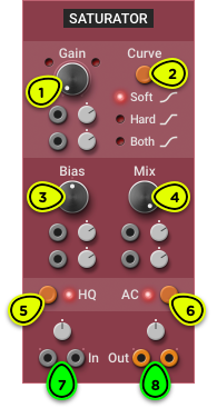
- Gain Knob Sets the input signal gain to adjust the amount of saturation.
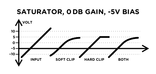
- Curve Selector Switches between soft, hard, and asymmetric (both soft and hard) clipping.
- Bias Knob Applies a bias to the saturation curve, changing the harmonic content of the saturation.
- Mix Knob Adjusts the amount of dry and saturated signal in the output.
- High Quality Switch Enables or disables oversampling.
- AC Coupling Switch Enables or disables a DC-blocking filter at the output.
- Inputs Signal to be saturated (stereo), with input level trim knob.
- Outputs Saturated signal (stereo), with output level trim knob.
Overview ⚓︎
The Saturator is a straightforward saturation module. As the Gain knob is turned clockwise, the amount of distortion in the output signal will increase. See Gain Staging for gain calibration tips.
Different saturation tones can be obtained by using the Curve and Bias settings.
Distortion can cause aliasing to occur, which is heard as dissonant frequencies added to the signal. This is especially obvious in sounds with loud high frequencies, such as raw oscillators playing in upper octaves. The High Quality (HQ) switch enables oversampling to reduce the amount of aliasing in the audible frequency range and round out the sound. This is enabled by default when adding the module to a patch.
In Depth ⚓︎
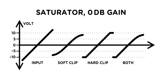
Saturation Curves ⚓︎
Soft
Soft clipping modeled on the behaviour of a differential transistor pair to produce a very smooth and musical distortion.
It starts adding subtle distortion even at a low input level, but doesn’t generate too much harsh high frequencies even at high gain. This saturation curve has an unmistakable analog sound.
Hard
Hard clipping, modeled after diode clipping.
The input signal passes through unchanged when it is below the clipping threshold, but gets fully clipped when it goes beyond the threshold. This is a harsh distortion that quickly adds a lot of high frequencies as soon as the signal is slightly clipped. This saturation curve sounds digital.
Both
Asymmetrical clipping that combines both soft clipping on positive voltages, and hard clipping on negative voltages.
Unlike the other two curves that only generate odd harmonics when Bias is centered, this will generate both even and odd harmonics which warm up the sound despite the harsh clipping on the lower half of the signal.
For most signals, the polarity of the soft and hard clip doesn’t matter. However, if you want to soft-clip the negative voltages and hard-clip the positive voltages, you can invert the polarity of the input and output of the Saturator with an Inverter’s Audio I/O.
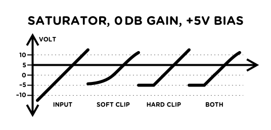
Bias ⚓︎
The Bias knob changes the center position of the saturation curves.
When centered, the soft and hard clipping curves will only generate odd harmonics if the input signal is symmetric, which can sound cold.
Turning the knob clockwise or counterclockwise will change the harmonic content of the distortion. Modulating the bias with a LFO can be an original way to add movement to the sound.
If the module is in hard clipping mode, biasing the curve by +10V or -10V will result in half-wave rectification, which means that the negative (resp. positive) part of the signal will be removed.
Too much bias can introduce an unwanted DC component in the output signal, reducing the headroom and making the level meter less accurate. The AC switch activates an internal DC-blocking filter that removes this DC component. We recommend always leaving it enabled unless the module is used to process CV signals.
Gain Staging ⚓︎
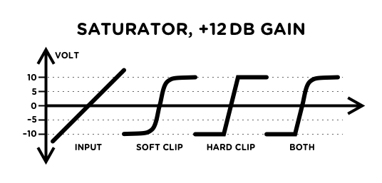
When Bias is centered, the output signal will never go beyond ±10V, no matter how much gain is applied. If the input signal is already hot, this may mean that there is audible distortion even when Gain is fully counterclockwise. Conversely, if the input is too low, turning the Gain knob clockwise may increase the volume instead of adding distortion.
To adjust the input level, use this procedure while a signal is going into the module:
- Set the Gain knob fully counterclockwise to 0 dB.
- Choose the desired saturation curve with the Curve button.
- Adjust the input level with the input trim knob until the saturation LED turns on.
- Dial back the input level so that the saturation LED remains off.
To compensate for the additional input gain, dial back the output trim knob by the same amount. For example, if you added 6 dB to the input, set the output to -6 dB.
Waveshaping ⚓︎
The Saturator module can be used as a waveshaper for oscillators. Instead of using it to add distortion near the output of a patch, connect it right at the output of an oscillator. Hard clipping can convert triangle waves and sawtooths into two different trapezoidal waveforms, while soft clipping can turn a triangle wave into a rich sine-like waveshape reminiscent of the sine wave on classic analog synths.
This can also be used on CV signals such as envelopes and LFO. In that case, High Quality mode can be disabled as it is useless on low frequency signals, and AC coupling must be disabled to ensure that low-frequency signals can pass through.
When using the saturator for waveshaping oscillators and LFOs, it can be a good idea to set the output to 50% to bring it back to the input’s original ±5V.