Gate Sequencer
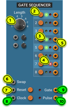
- Length Selector Adjusts the sequence length from 1 to 8 steps.
- Per-step Gate Switch Sets the gate output state for that step.
- Per-step Gate LED Shows whether the gate is enabled for that step.
- Active Step LED Shows which step is currently active.
- Per-step Output High (10V) when the step is active, low (0V) when the step is not active. Can be used to trigger other modules when the sequencer reaches a certain step.
- Swap Input Real-time sequence re-programming. When triggered, the state of the active step will be inverted.
- Reset Input When triggered, Gate and Pulse outputs are set to low (0V), all swapped steps are restored to their original state, and the next clock signal will start the sequence from the first step. Can be triggered manually with the push button.
- Clock Input When triggered, the sequencer advances to the next step. Can be triggered manually with the push button.
- Gate Output High (10V) if the active step is enabled, low otherwise. If the gate is enabled for two consecutive steps, the gate output remains high.
- Pulse Output Like the Gate output, but only remains high (10V) for as long as the input Clock signal is high. Guaranteed to go low (0V) between each step.
Overview ⚓︎
The Gate Sequencer is an eight-step sequencer designed to trigger other modules in a rhythmic pattern.
Thanks to the per-step outputs, which are triggered every time a step is reached, a single sequencer can be used to trigger many different modules.
In Depth ⚓︎
Playing ⚓︎
The sequencer doesn’t work by itself; it needs a clock signal. It will advance by one step every time a trigger signal is detected on the Clock input, or when the push button next to the Clock input is pressed.
The Clock input will usually be connected to the Clock output of the Master Clock or of a Clock module, although it could be connected to a LFO or any kind of gate or trigger, such as the Gate output of the Keyboard.
The red LED to the right of each step shows the active step. No step is active until the first clock signal is received after the sequencer has been reset.
In the image of the module at the top of this section, the active step is step 7.
When the sequence reaches the last step, it will loop back to the first step. The length of the sequence can be adjusted with the Length selector, and can even be modulated while the sequence is playing for some interesting polyrythmic effects.
Outputs ⚓︎
Every time a new step becomes active, its gate state is routed to the Gate and Pulse outputs.
If the active step’s gate is enabled (green LED), the Gate output will be high (10V) for as long as the step remains active, and the Pulse output will be high for as long as the Clock input is high.
Use the Gate output if you need a continuous gate spanning multiple steps, and the Pulse output if you need the gate to be retriggered at every step.
The per-step outputs are triggered every time a step becomes active, even if its gate is not enabled. They can be used to trigger any module such as the ADSR or Pulse, this making it possible to control many different parts from a single sequencer.
You can connect the outputs from multiple steps to one or more Mix 8 or Dual Mix modules and create as many rhythmic patterns as you want from a single sequencer. This can be messier than using many sequencers because of all the wires it takes, but it leaves more free rack space for other modules.
Resetting ⚓︎
The sequencer will return to its initial state when the Reset input is triggered, or when the Reset push-button is pressed. After a reset, the next clock signal will play the first step.
Step Swapping (Real-time Re-programming) ⚓︎
When the Swap input is triggered, the state of the gate on the currently active step will be inverted.
Using this input, the sequence can be re-programmed while it is running. For example, you could connect it to a slow LFO or to a low-density noise source to occasionally change a step.
By connecting a step’s output trigger to the Swap input, that step’s state will change every time the sequence plays.
When the Reset input is triggered, the sequence will revert all steps to their original, non-swapped state.
If you want to reprogram the sequence manually after using the Swap input, you should click on the Reset button first. Otherwise, you may be surprised to see steps you have just programmed change their value the next time the sequence is reset.
The swapped values are not saved in patches; only the original state is saved.